
Temperature control equipment and heat exchange unit thereof

A technology of heat exchange unit and temperature control equipment, which is applied in the direction of lighting and heating equipment, electrical equipment structural parts, electrical components, etc., and can solve problems such as increased costs, assembly errors, and increased man-hours

Pending Publication Date: 2020-07-07
DELTA ELECTRONICS INC
View PDF5 Cites 0 Cited by
  • Summary
  • Abstract
  • Description
  • Claims
  • Application Information

AI Technical Summary

Problems solved by technology

[0003] Existing heat dissipation equipment such as hybrid air conditioners is to install the heat pipe heat exchanger and the air conditioning heat exchanger together to achieve the function of two machines, but it needs to include more than two heat pipe heat exchangers. The pipeline configuration is complex and requires the use of components such as pipeline path switching valves and expansion valves, and the complicated pipelines must be connected by welding, which not only increases costs and man-hours, but also easily causes assembly errors

Method used


Image

  • Temperature control equipment and heat exchange unit thereof
  • Temperature control equipment and heat exchange unit thereof
  • Temperature control equipment and heat exchange unit thereof

Examples


Embodiment Construction

[0041] The preferred embodiments of the temperature control device and the heat exchange unit according to the present invention will be described below with reference to the relevant drawings, wherein the same components will be described with the same reference numerals.

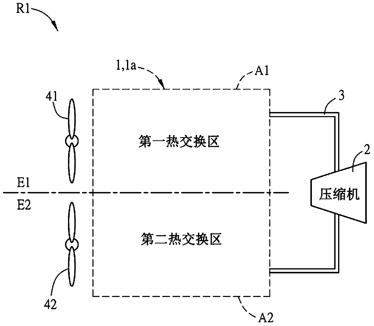
[0042] Please refer to figure 1 and Figure 2A , figure 1 It is a schematic diagram of a preferred embodiment of the temperature control device R1 of the present invention. The temperature control device R1 in the figure is set in the first environment E1 and the second environment E2. The temperature control device R1 includes a heat exchange unit 1 / 1a, a compressor 2, a circulation loop 3 and a working fluid. The heat exchange unit 1 / 1a is divided into a first heat exchange area A1 and a second heat exchange area A2.

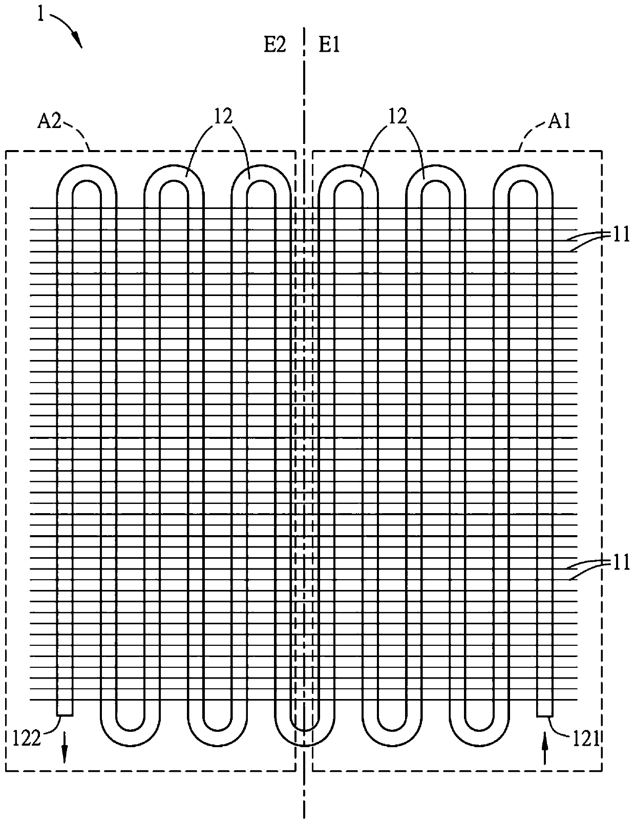
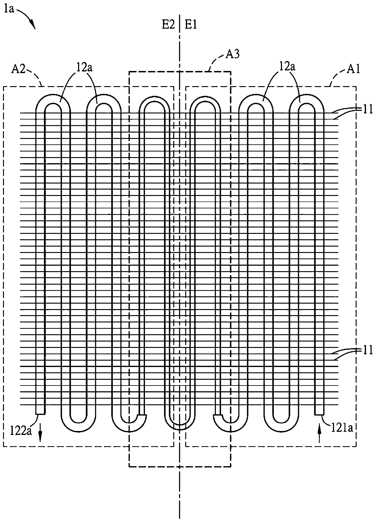
[0043] Please refer to Figure 2A and also refer to figure 1 , Figure 2A for figure 1 A schematic diagram of a first embodiment of the heat exchange unit 1 of the temperature contr...


PUM


Abstract

The invention provides temperature control equipment which is arranged in a first environment and a second environment. The temperature control equipment comprises a heat exchange unit, a compressor,a circulation loop and a working fluid. The heat exchange unit is divided into a first heat exchange area and a second heat exchange area, the heat exchange unit comprises a plurality of radiating fins and at least one pipeline, the pipeline firstly runs in the first heat exchange area and then runs in the second heat exchange area, the radiating fins are used for radiating heat, the first heat exchange area is correspondingly arranged in the first environment, and the second heat exchange area is correspondingly arranged in the second environment. The circulation loop communicates with the heat exchange unit and the compressor. The working fluid is located in the circulation loop, and the compressor works on the working fluid, so that the working fluid performs a temperature regulation and control function.

Description

technical field [0001] The present invention relates to a temperature control device and its heat exchange unit, in particular to a heat exchange unit having both the functions of a condenser and an evaporator. Background technique [0002] Electronic communication equipment, power converters, or spare batteries are placed inside the traditional communication cabinet. The cabinet body is mostly made of metal material, and the inside and outside of the cabinet are isolated from dust and water to protect the electronic components in the cabinet. The inside of the cabinet is a closed space, and heat dissipation equipment is usually installed on the cabinet to prevent the temperature inside the cabinet from being too high. [0003] Existing heat dissipation equipment such as hybrid air conditioners is to install the heat pipe heat exchanger and the air conditioning heat exchanger together to achieve the function of two machines, but it needs to include more than two heat pipe h...

Claims


Application Information

Patent Timeline
Patent Type & Authority Applications(China)
IPC IPC(8): F25B1/00F25B39/00
CPCF25B1/005F25B39/00F25B2500/09F28D15/043F28D15/0266F28D1/0443F28D2021/0028F28D2021/0068H05K7/20309H05K7/20318
Inventor 潘学奇汪则鑫陈加伟陈英琦
Owner DELTA ELECTRONICS INC
Learn More