Heat supply unit energy-saving retrofit system and energy-saving operation control method thereof

A technology for energy-saving transformation and heating units, which is applied in heating systems, hot water central heating systems, space heating and ventilation details, etc. Pressure and other issues

Pending Publication Date: 2020-07-07
内蒙古思铂睿特节能科技有限公司 +1
View PDF0 Cites 0 Cited by
  • Summary
  • Abstract
  • Description
  • Claims
  • Application Information

AI Technical Summary

Problems solved by technology

However, the heat exchange station system and heat exchange unit ( figure 1 shows the structure of a traditional typical central heating system), there are certain defects in the system structure and operating process, which lead to problems such as energy waste and poor economy in the operation of the central heating system; the specific performance is:
[0003] 1. The existing heat exchange station or heat exchange unit is usually designed according to the parameters that the ratio of the temperature difference of the secondary side (ie: low temperature side) to the temperature difference of the primary side (ie: high temperature side) is greater than 3:1 or higher , the length-to-width ratio of the heat exchanger plate is small, which generally causes the heat exchanger to have a large heat exchange area margin, insufficient heat exchange, and low flow rate on the primary side, which leads to the primary side of the heat exchanger It is easy to deposit impurities, scale or blockage in the flow channel, which seriously reduces the reliability of the equipment itself and the operation of the entire heating system
[0004] 2. The heat exchangers, circulating water pumps, pipeline connection equipment, and heat user systems in the low-temperature side circulation system of the existing heat exchange station or heat exchange unit are all connected in series, and the flow rate of the secondary side circulating water flowing through each part is The same; when it is necessary to meet the circulating pressure difference of the secondary network heat user system, the flow through the low-temperature side must be relatively large. Therefore, not only cannot take advantage of the large heat exchange area margin of the heat exchanger, but also easily cause low temperature The problem of high internal cycle power consumption of the side heat exchange system
[0005] 3. In order to reduce manufacturing costs, in the low-temperature side circulation system of the existing heat exchange station or heat exchange unit, the diameters of the connecting pipelines of each component equipment are generally small, so it is easy to cause the heat exchange station to be damaged due to excessive local resistance. And the invalid power consumption of the unit operation is relatively large
[0006] 4. Existing heat exchange stations or heat exchange units usually operate in parallel with multiple heat exchangers, so that the high-temperature medium stays in the heat exchanger for a short time, making it difficult to achieve sufficient heat exchange, resulting in high temperature in the central heating system The side circulation temperature difference is relatively small, which seriously restricts the heat transfer capacity of the high temperature side pipe network
[0007] 5. The existing heat exchange station or heat exchange unit cannot realize fine adjustment of the central heating system due to the single design function of the process structure, and the control of the operating parameters of the low temperature side of the heat exchange station or heat exchange unit can only be controlled by the electric control valve on the high temperature side For control, when the heating temperature on the high temperature side is high, only the control method of reducing the opening of the electric control valve on the high temperature side of the heat exchange station or heat exchange unit can be used. Once a certain number of heat exchange stations or heat exchange units When the same control method is adopted, it is easy to cause an instantaneous pressure increase in the central heating system, which in turn affects the operation safety of the high temperature side of the central heating system
Therefore, installing a check valve at the outlet of the circulation pump of the heat exchange system will not only cause a waste of investment, but also increase the ineffective power consumption of the circulation pump.
[0009] 7. In the existing central heating system, the phenomenon of temperature fluctuation on the high temperature side is often or likely to occur. Once the temperature of the heating network on the high temperature side suddenly rises, the heat exchange rate of the heat exchange station or the heat exchange unit will increase instantaneously, which is very It is easy to cause an instantaneous pressure increase or even overpressure in the low-temperature side pipe network of the heating system, threatening the safety of the low-temperature side system
For this situation, most of the existing heat exchange stations or heat exchange units only use low-temperature side drainage and pressure relief for treatment, which brings serious waste of water resources and pollution of groundwater.

Method used


Image

  • Heat supply unit energy-saving retrofit system and energy-saving operation control method thereof
  • Heat supply unit energy-saving retrofit system and energy-saving operation control method thereof
  • Heat supply unit energy-saving retrofit system and energy-saving operation control method thereof

Examples


Embodiment Construction

[0033] The embodiments of the present invention will be described in detail below with reference to the accompanying drawings, but the present invention can be implemented in many different ways defined and covered by the claims.

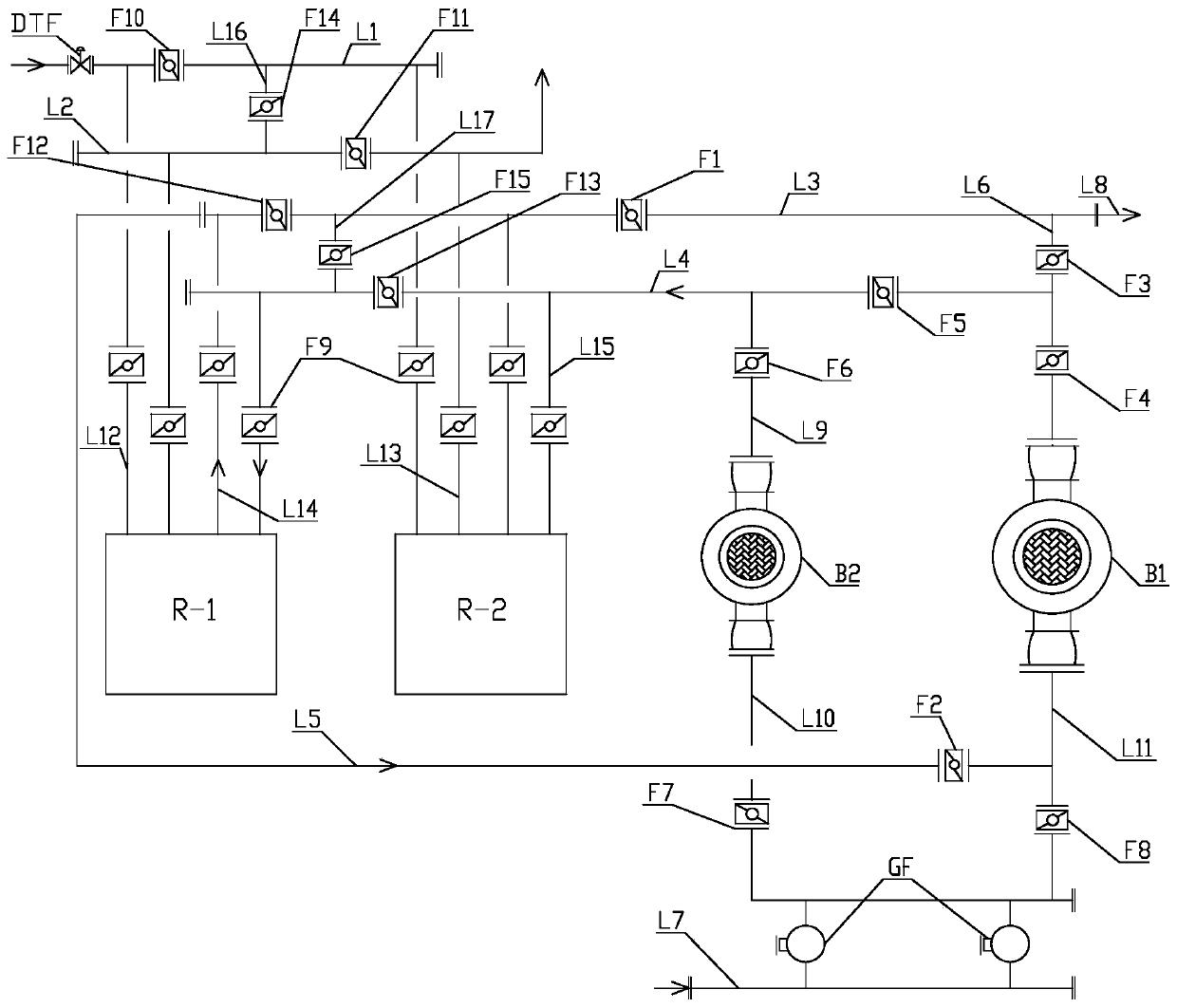
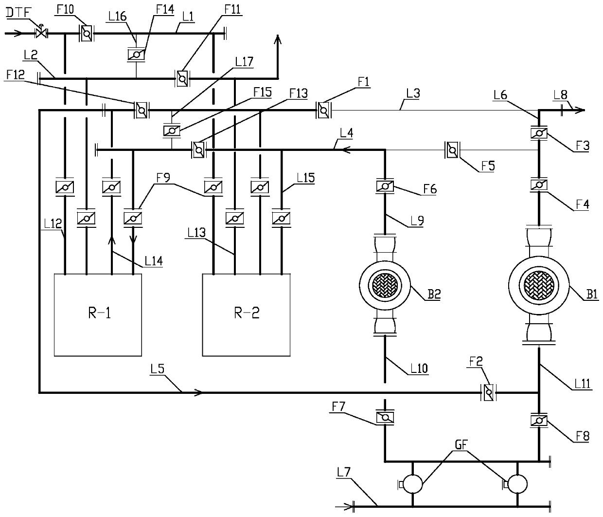
[0034] Such as figure 2 As shown, an energy-saving transformation system for a heating unit provided in this embodiment includes a high-temperature side water inlet pipe L1, a high-temperature side water outlet pipe L2, a low-temperature side water outlet pipe L3, a low-temperature side water inlet pipe L4, and a low-temperature side water outlet pipe. Bypass pipe L5, low temperature side inlet and outlet water bypass pipe L6, secondary network return water main pipe L7, secondary network water supply main pipe L8, heat exchange module, secondary network circulation pump B1 and heat exchange circulation pump B2; among them, heat exchange The water inlet on the high temperature side of the module is connected to the water inlet pipe L1 on the high t...


PUM


Abstract

The invention discloses a heat supply unit energy-saving retrofit system and an energy-saving operation control method thereof. The heat supply unit energy-saving retrofit system includes a high temperature side water inlet main pipe, a high temperature side water outlet main pipe, a low temperature side water outlet main pipe, a low temperature side water inlet main pipe, a secondary network circulating pump, a heat exchange circulating pump, a secondary network backwater main pipe, a secondary network water supply main pipe, a heat exchange module, a low temperature side water outlet bypasspipe which communicates a low temperature side water outlet of the heat exchange module with a water suction port of the secondary network circulating pump, a low temperature side water inlet and outlet water bypass pipe which communicates a water outlet of the secondary network circulating pump with the low temperature side water outlet main pipe and a shutoff valve arranged on a corresponding pipeline. According to the heat supply unit energy-saving retrofit system and the energy-saving operation control method thereof, on the basis of a traditional typical central heat supply unit, a new heat supply system structure and an operation mode are formed by retaining the secondary network circulating pump, increasing the heat exchange circulating pump and associated pipelines and valves thereof, and removing a check valve on the water outlet side of a check bypass pipe and the secondary network circulating pump, the operation and regulation are more flexible, and the operation energy consumption is significantly reduced.

Description

technical field [0001] The invention relates to the technical field of heating and heating, in particular to an energy-saving renovation system for a heating unit and an energy-saving operation control method for the system. Background technique [0002] With the continuous expansion of the scale of urban central heating, the heat exchange station system and heat exchange unit in the central heating system are more and more popularized and applied. However, the heat exchange station system and heat exchange unit ( figure 1 shows the structure of a traditional typical central heating system), there are certain defects in the system structure and operating process, which lead to problems such as energy waste and poor economy in the operation of the central heating system; the specific performance is: [0003] 1. The existing heat exchange station or heat exchange unit is usually designed according to the parameters that the ratio of the temperature difference of the secondary...

Claims


Application Information

Patent Timeline
IPC IPC(8): F24D3/02F24D3/10F24D19/10
CPCF24D3/02F24D3/1058F24D19/1015
Inventor 周浩武晓卿
Owner 内蒙古思铂睿特节能科技有限公司
Why Eureka
Try Eureka