
Release liners for laser cut adhesives

A release liner, adhesive layer technology, applied in the direction of adhesive types, ester copolymer adhesives, film/sheet adhesives, etc., can solve problems such as damage to the adhesive layer, and achieve low The effect of peeling force

Active Publication Date: 2020-07-03
3M INNOVATIVE PROPERTIES CO
View PDF4 Cites 0 Cited by
  • Summary
  • Abstract
  • Description
  • Claims
  • Application Information

AI Technical Summary

Problems solved by technology

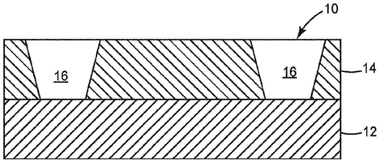
However, cutting the adhesive (e.g., with a laser) may result in cutting or at least melting a portion of the release liner, which may result in a tighter bond between the adhesive and the release liner
When the release liner is removed, breaking the tight bond between the adhesive and the release liner can cause the adhesive to remain adhered to the release liner, damaging the adhesive layer

Method used


Image

  • Release liners for laser cut adhesives
  • Release liners for laser cut adhesives
  • Release liners for laser cut adhesives

Examples


Embodiment 1

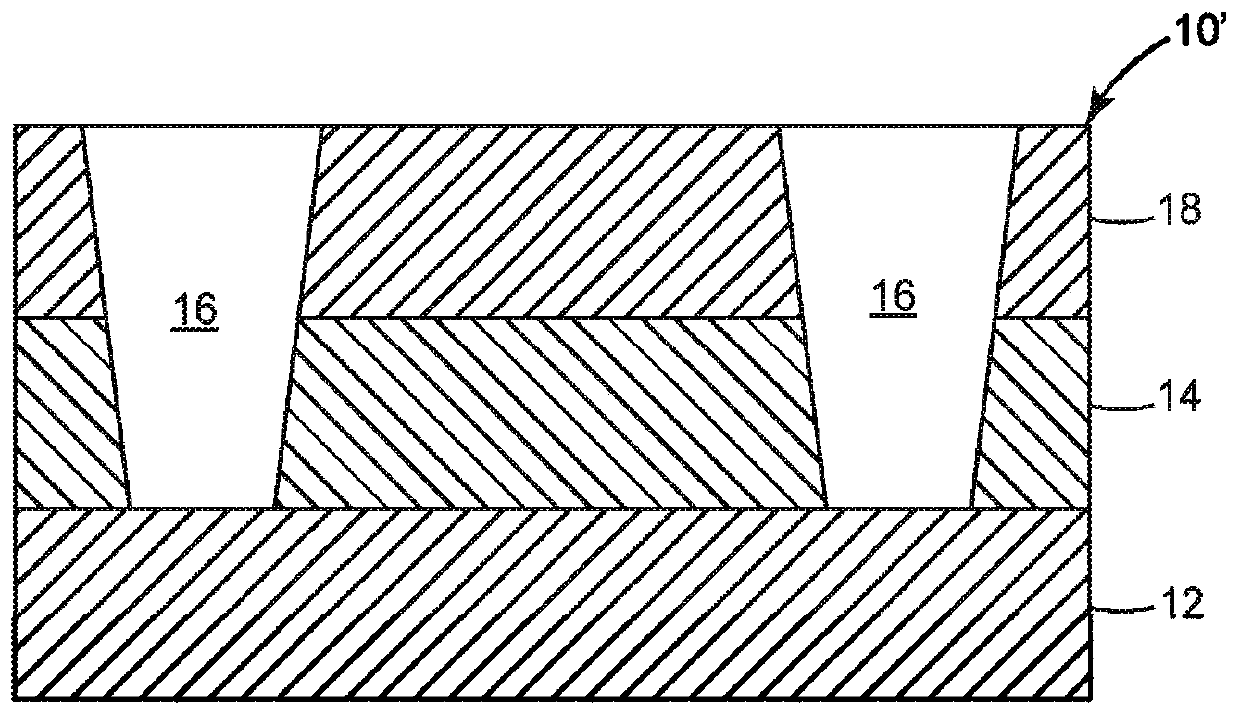
[0123] Adhesive layer 14 is a 25 micron acrylic foldable component layer as described in PCT Patent Publication No. WO 2016 / 196541 (Behling et al.), the disclosure of which is incorporated herein by reference, entitled "Example 7- 20: Preparation of solvent-free based component layer samples" and details are those of Example 8 in Table 3. The adhesive is in the form of a laminate 10' between a 75 micron silicone coated low peel secondary liner 18 that adheres to standard substrates such as polyethylene (PET) (the composite will be the device specific) (obtained from SKC Haas, Seoul, South Korea (SKCHaas, Seoul, South Korea) under the trade designation "RF02N") and 100 microns of addition cured silicone release-coated biaxially oriented polypropylene (BOPP) low Between the release type first liner 12.

[0124] The laminate was exposed to sufficient laser electromagnetic radiation to produce a 25.4 mm x 203.2 mm rectangular continuous profile cut through the second release line...

Embodiment 2

[0127] Example 2 was prepared as described in Example 1 except that the adhesive was in the form of a laminate 10' between a 75 micron silicone coated PET low peel secondary liner 18 (RF02N) and 100 Micron addition cured silicone release coated BOPP high release first liner 12 between.

Embodiment 3

[0129] Example 3 was prepared as described in Example 1, except that the adhesive was in the form of a laminate 10", between a 75 micron silicone-coated PET low-release secondary liner 18 (RF02N) and 75 Micron silicone coated PET high release first liner 12 (available from SKC Haas under the trade designation "RF12N").


PUM


Abstract

Various embodiments described herein relate to a laminate. The laminate includes a release liner comprising at least one polyolefin and an adhesive layer. The adhesive layer contacts a region of a first major surface of the release liner. Upon exposure to laser electromagnetic radiation, the adhesive layer is configured to absorb at least 55% (in some embodiments, at least 60%, 65%, 70%, 75%, 80%,85%, 90%, 95%, or even 100%) of the laser electromagnetic radiation and the release liner absorbs no greater than 45% (in some embodiments, no greater than 40%, 35%, 30%, 25%, 20%, 15%, 10%, 5%, or even 0%) of the laser electromagnetic radiation.

Description

[0001] Cross References to Related Applications [0002] This application claims the benefit of U.S. Provisional Patent Application No. 62 / 589,266, filed November 21, 2017, the disclosure of which is incorporated herein by reference in its entirety. Background technique [0003] The adhesive can be deposited on a release liner prior to application to the final substrate. The adhesive may be cut into predetermined shapes prior to application to the final substrate. However, cutting the adhesive (eg, with a laser cutting the adhesive) may result in cutting or at least melting a portion of the release liner, which may result in a tighter bond being formed between the adhesive and the release liner. When the release liner is removed, breaking the tight bond between the adhesive and the release liner can cause the adhesive to remain adhered to the release liner, thereby damaging the adhesive layer. Contents of the invention [0004] Various disclosed embodiments relate to lami...

Claims


Application Information

Patent Timeline
IPC IPC(8): C09J7/38C09J7/40
CPCC09J7/00C09J2423/005C09J7/38C09J7/401C09J2301/18C09J9/00C09J2301/312C09J7/385C09J7/30Y10T428/1476C09J7/20C09J133/08Y10T428/2848Y10T428/14
Inventor 安德鲁·J·施托克霍尔姆乔舒亚·J·洛加艾伯特·I·埃费拉茨
Owner 3M INNOVATIVE PROPERTIES CO
Learn More