Polishing device for automobile clutch brake disc

A technology of polishing device and brake disc, applied in grinding/polishing safety device, grinding driving device, grinding/polishing equipment, etc., can solve the problems affecting grinding and polishing accuracy, low efficiency, time-consuming and labor-intensive, etc. Replacing the polishing head, the device is safe to use, and the effect of high dust removal efficiency

Active Publication Date: 2020-07-03
莱州伟辰汽车配件有限公司
View PDF6 Cites 0 Cited by
  • Summary
  • Abstract
  • Description
  • Claims
  • Application Information

AI Technical Summary

Problems solved by technology

[0003] After the brake disc is used for a long time, the brake surface will appear uneven. At this time, the brake disc needs to be repaired, polished and polished. In the prior art, manual grinding and polishing is generally used, but this method is time-consuming, laborious, inefficient, and the polishing is not enough. Smooth; therefore, there are many devices capable of automatic grinding and polishing
[0004] However, when this kind of automatic grinding and polishing equipment is in use, it is generally done by grinding and polishing in the box, and the splashed powder is left in the box, or a dust collection device is installed on the box to solve this problem, but it still cannot be cleaned in time. , Completely extract the dust generated at the grinding place, so that the powder generated by grinding sticks to the brake disc or the grinding head, which especially affects the grinding and polishing accuracy

Method used


Image

  • Polishing device for automobile clutch brake disc
  • Polishing device for automobile clutch brake disc
  • Polishing device for automobile clutch brake disc

Examples


Embodiment Construction

[0032] The implementation mode of the present invention is illustrated by specific specific examples below, and those who are familiar with this technology can easily understand other advantages and effects of the present invention from the contents disclosed in this description. Obviously, the described embodiments are a part of the present invention. , but not all examples. Based on the embodiments of the present invention, all other embodiments obtained by persons of ordinary skill in the art without making creative efforts belong to the protection scope of the present invention.

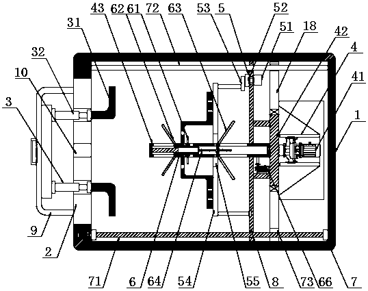
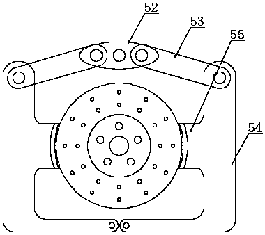
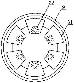
[0033] Refer to the attached Figure 1-7 , a polishing device for an automobile clutch brake disc in this embodiment includes a body 1 and a door panel 2, the door panel 2 is arranged on the front side of the body 1 and is hingedly connected with the body 1, and a brake disc is slidingly arranged inside the body 1 Clamping and vacuuming mechanism, the door panel 2 is provided with a polishing co...


PUM


Abstract

The invention discloses a polishing device for an automobile clutch brake disc, and relates to the field of brake disc repair. The polishing device comprises a machine body and a door plate, wherein the door plate is arranged at the front side of the machine body and is in hinged connection to the machine body; a brake disc clamping and dust-sucking mechanism is horizontally arranged inside the machine body in a sliding mode; a polishing assembly which corresponds to the brake disc clamping and dust-sucking mechanism is arranged on the door plate; and the brake disc clamping and dust-sucking mechanism comprises a rotary polishing drive assembly, a clamping assembly, front and rear dust-sucking assemblies as well as front and rear moving assemblies. The front and rear dust-sucking assemblies are arranged, so that in and out, positioning and clamping of the brake disc are not affected, and dust-sucking devices do not need to independently control; insertion and pull-out work, on a positioning tube, of the brake disc can be utilized to realize inclination and storage of the two dust-sucking plates, so that dust generated at the two sides of the brake disc can be timely sucked during inclination; and eight dust-sucking plates are arranged in a two-umbrella surrounding mode, so that powder generated by grinding can be completely and efficiently sucked, and therefore, dust removal efficiency is high.

Description

technical field [0001] The embodiment of the present invention relates to the field of brake disc repair, in particular to a polishing device for an automobile clutch brake disc. Background technique [0002] The brake disc, in simple terms, is a round disc that rotates when the car is moving. The brake caliper clamps the brake disc to generate braking force. When the brake is applied, it clamps the brake disc to slow down or stop the car. [0003] After the brake disc is used for a long time, the brake surface will appear uneven. At this time, the brake disc needs to be repaired, polished and polished. In the prior art, manual grinding and polishing is generally used, but this method is time-consuming, laborious, inefficient, and the polishing is not enough. Smooth; therefore, there are many equipment that can automatically polish and polish. [0004] However, when this kind of automatic grinding and polishing equipment is in use, it is generally done by grinding and poli...

Claims


Application Information

Patent Timeline
Patent Type & Authority Applications(China)
IPC IPC(8): B24B29/02B24B41/04B24B41/06B24B47/20B24B47/22B24B55/06
CPCB24B29/02B24B41/04B24B41/06B24B47/20B24B47/22B24B55/06
Inventor 提云贵裴鸿昌李金蓬
Owner 莱州伟辰汽车配件有限公司
Why Eureka
Try Eureka