
Method used for superspeed laser cladding of end face of disc type part

A disc-like parts, laser cladding technology, applied in metal material coating process, coating, etc., can solve the problems of less ultra-high-speed laser cladding, less research on the end face cladding process of disc parts, etc.

Active Publication Date: 2020-06-26
JIANGSU UNIV
View PDF6 Cites 5 Cited by
  • Summary
  • Abstract
  • Description
  • Claims
  • Application Information

AI Technical Summary

Problems solved by technology

[0005] At present, there are few domestic data on ultra-high-speed laser cladding, and it is generally used in the processing of the outer circle of shaft parts, and there are few studies on the end face cladding process of disc parts.

Method used


Image

  • Method used for superspeed laser cladding of end face of disc type part
  • Method used for superspeed laser cladding of end face of disc type part
  • Method used for superspeed laser cladding of end face of disc type part

Examples


Embodiment

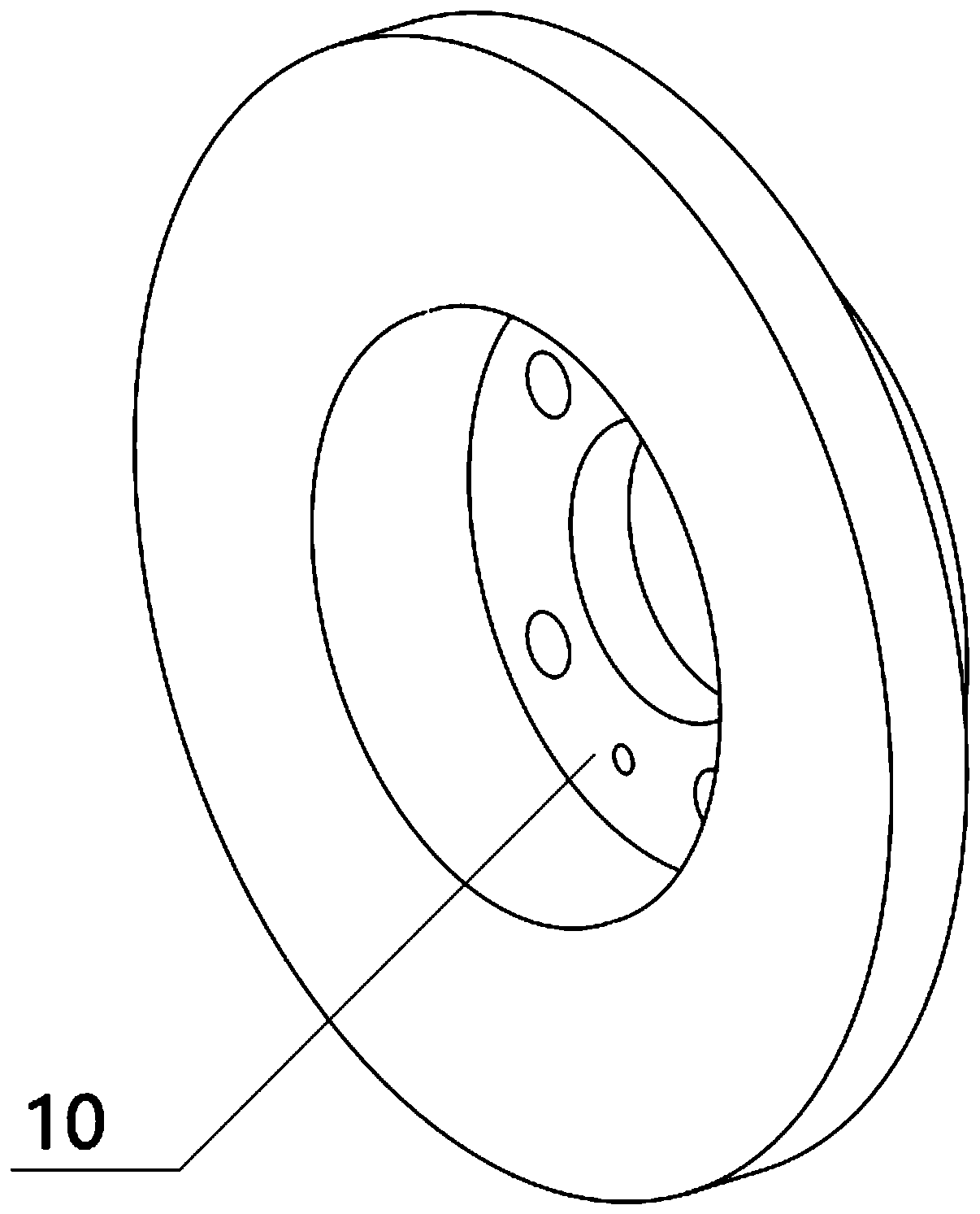
[0068] For a certain type of brake disc, the end surface to be clad is circular, with an outer diameter of Φ800mm, an inner diameter of Φ200mm, a thickness of 30mm, and a base material of 35CrMo. The surface is subjected to single-layer ultra-high-speed laser cladding, and the cladding powder is selected Iron-based stainless steel powder, the cladding process is carried out through the following process steps:

[0069] S1. Carry out machining treatment on the end surface of the brake disc, check the end surface of the brake disc to ensure that the surface quality is free from defects.

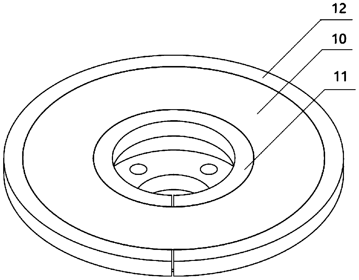
[0070] S2, install the customized notched ring I and notched ring II on the outer circle and inner hole of the brake disc. The notch width of the notched ring I used is 1mm, the inner diameter of the notched ring I is Φ800mm, the outer diameter is Φ810mm, and the thickness is 10mm. The inner ring of the notched ring I is provided with a rectangular groove with a depth of 3mm and a width of 3mm....


PUM

PropertyMeasurementUnit
widthaaaaaaaaaa
depthaaaaaaaaaa
widthaaaaaaaaaa

Abstract

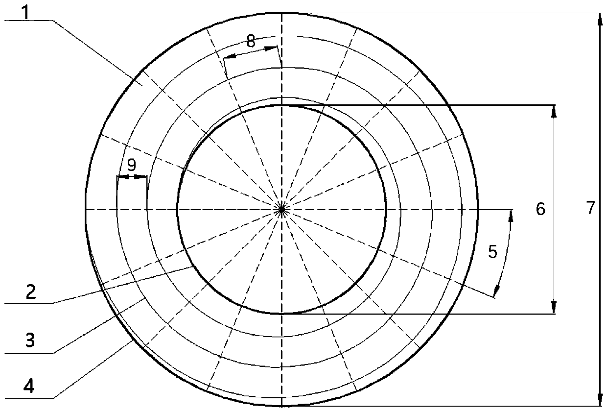
The invention relates to a method used for superspeed laser cladding of an end face of a disc type part. The method comprises the steps that a gap ring I and a gap ring II are mounted on an outer circle and an inner hole of the disc type part in a sleeving manner, and according to process needs, the cladding rate V1, the cladding lap-joint rate eta, laser beam power P and other parameters are set;according to the cladding lap-joint rate eta, the superspeed laser cladding single way width DL and other parameters, a superspeed laser cladding path is planned that a starting point is located on the section line of an inner hole of the end face of the disc type part, and an end point is located on an equal-distance spiral line on the section line of the outer circle of the end face of the discpart; equal-angle joints are mounted at the same time, the equal-distance spiral line is divided into multiple segments of equal-distance spiral line arcs, and through the manner of changing the disctype part rotating angle speed omega i and the superspeed laser cladding head moving speed during superspeed laser cladding of the all segments of equal-distance spiral line arcs, cladding is carriedout, and it is ensured that in the cladding process, the parameters are kept stable; and finally, through a linear cutting manner, the gap ring I, the gap ring II and the disc type part are separated.

Description

technical field [0001] The invention relates to laser cladding technology, in particular to a method for ultra-high-speed laser cladding on the end faces of disk parts. Background technique [0002] In 2017, the Ultra High-Speed ​​Laser Cladding technology (Ultra High-Speed ​​Laser Cladding) was proposed by the Fraunhofer Institute in Germany. The cladding rate can reach 25-200m / min. During the processing, the laser is focused on the workpiece, so that most of the energy acts The powder above the workpiece, using this method, the heat input of the matrix during the cladding process is extremely small, but it can ensure sufficient metallurgical bonding between the powder and the matrix, and the general dilution rate is only about 2 to 4%. Therefore, ultra-thin and high-quality coatings can be prepared. According to different cladding rates, the thickness of the coating is basically only between 25 and 400 μm, and the surface finish of the coating is very good. It can be put i...

Claims


Application Information

Patent Timeline
Patent Type & Authority Applications(China)
IPC IPC(8): C23C24/10
CPCC23C24/10
Inventor 鲁金忠杜家龙徐祥仇金欣罗开玉
Owner JIANGSU UNIV
Learn More