
Laser cladding cooling device with fin type cooling fins

A laser cladding and cooling device technology, which is applied in household refrigeration devices, lighting and heating equipment, metal material coating technology, etc., can solve the problem of ineffective cooling and heat dissipation of workpieces, limited size and structure of workpieces, and cooling effect of workpieces. Inconspicuous problems, to achieve the effect of heat dissipation, improve molding quality, and ensure cladding efficiency

Active Publication Date: 2020-12-29
SOUTHEAST UNIV
View PDF8 Cites 0 Cited by
  • Summary
  • Abstract
  • Description
  • Claims
  • Application Information

AI Technical Summary

Problems solved by technology

The use of this device can cool down the workpiece during the laser cladding process, but there are several shortcomings: First, the temperature of the laser processing head is high. The water temperature will rise accordingly, and the effect of cooling the workpiece through heat exchange is not obvious; the second is that the cooling water pipe does not directly contact the workpiece or the substrate, but has a certain distance from the workpiece, and the cooling effect of the workpiece is not obvious; the third is near the laser processing head. While the cooling pipe cools and dissipates heat from the workpiece, it may affect the processing position of laser cladding
During the laser cladding process, the device can have a certain heat dissipation and cooling effect on the substrate, and can protect the workpiece from being oxidized, but there are two shortcomings: one is that the device dissipates heat through the S-shaped cooling channel at the bottom of the substrate, and the side of the substrate dissipates heat. There is no corresponding cooling structure, the cooling water is circulating water, and the cooling water that takes away the heat of the substrate flows out of the cooling water channel and only dissipates heat through the cooling fins. There is no corresponding cooling equipment. If the laser cladding workpiece has a long processing cycle, the substrate will be damaged. The cooling effect will be weakened; the second is that the substrate is placed at the bottom of the cooling and protection device. During laser processing, the structure and size of the cooling and protection device will affect the movement of the powder head, so the size and structure of the workpiece will be greatly limited.

Method used


Image

  • Laser cladding cooling device with fin type cooling fins
  • Laser cladding cooling device with fin type cooling fins
  • Laser cladding cooling device with fin type cooling fins

Examples


Embodiment

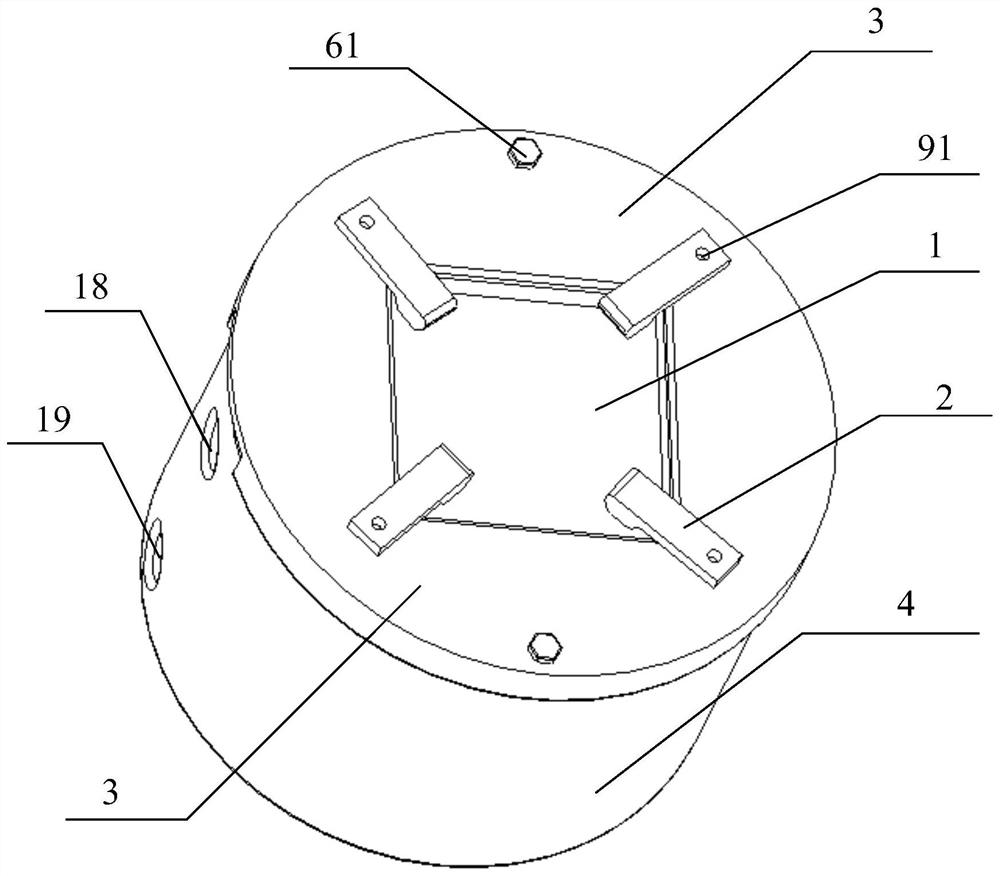
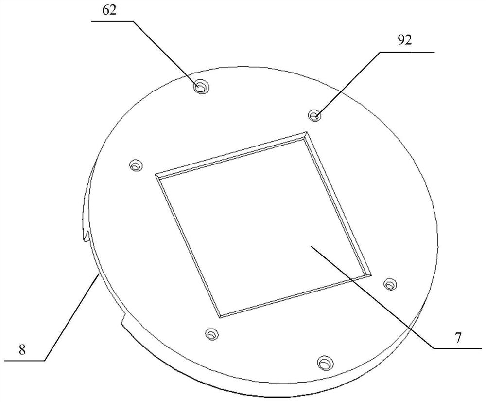
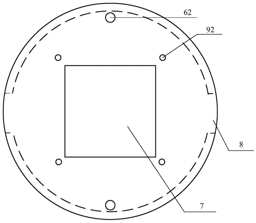
[0060] The present invention proposes an all-round and efficient forced cooling device for laser cladding substrates, the overall structure of which is as follows figure 1 As mentioned above, the cooling device includes a cooling plate 1 , a fixture 2 , a protective cover 3 , a cooling water tank 4 and a finned cooling fin 5 . The protective cover 3 is threadedly connected with the cooling plate 1 and the heat dissipation water tank 4, and a gasket is installed at the junction; The size of the square hole 7 set at the center of the main body of the protective cover 3 is the same as that of the base plate, and the side is provided with a side gap 8 slightly larger than the cooling water inlet channel 10 and the cooling water inlet channel 11; the four corners of the square hole 7 are provided with threaded holes d12 for easy fastening The bolt 61 passes through to install the fixture 2, and the protective cover 3 on the left and right sides of the square hole 7 is provided with...


PUM


Abstract

The invention discloses a laser cladding cooling device with fin type cooling fins. The laser cladding cooling device comprises a workpiece cooling disc capable of dissipating heat, a clamp and a heatdissipation water tank. A water tank cooling water inlet channel and a water tank cooling water outlet channel are formed in the side wall of the heat dissipation water tank. The workpiece cooling disc capable of dissipating heat comprises a disc-shaped body and the fin type cooling fins. A workpiece containing part is arranged in the middle of the front face of the disc-shaped body, two annularcooling water channels are concentrically arranged on the periphery of the workpiece containing part, and the disc-shaped body is provided with a cooling disc cooling water inlet channel and a coolingdisc cooling water outlet channel in the radial direction. The fin type cooling fins are arranged on the back surface of the disc-shaped body. A protective cover is connected to the open end of the heat dissipation water tank in a sealed manner and wrapped on the disc-shaped body, and a through hole a is formed in the middle of the protective cover. The through hole a is right opposite to the workpiece containing part, and two or more clamps are evenly arranged on the outer side of the protective cover. Thus, by means of the laser cladding cooling device with the fin type cooling fins, a baseplate (workpiece) can be comprehensively and efficiently cooled, and the machining quality of a laser cladding formed part is improved.

Description

technical field [0001] The invention relates to the field of laser cladding, in particular to a high-efficiency cooling device for laser cladding, which is suitable for laser cladding molding of fine-grain structure parts and thin-walled parts. Background technique [0002] Laser cladding, also known as laser cladding or laser cladding, is a technology that subverts the evolution of traditional manufacturing concepts to modify the surface. It feeds the cladding layer material onto the surface of the substrate by adding powder in different forms, and the temperature of the powder rises and melts after being irradiated by the laser, and falls into the molten pool formed on the surface of the substrate due to the high temperature of the laser. After air-cooling and solidification, the surface cladding layer exhibits good metallurgical bonding with the substrate. Through this method of adding a surface coating with required performance on the surface of the base body, not only ...

Claims


Application Information

Patent Timeline
Patent Type & Authority Applications(China)
IPC IPC(8): C23C24/10F25D1/02
CPCC23C24/10F25D1/02Y02P10/25
Inventor 孙桂芳杨坤倪中华卢轶王占栋
Owner SOUTHEAST UNIV
Learn More