
Micro-lens group for obtaining adjustable annular light beam

A ring beam and micro lens technology, applied in the direction of condenser, optics, optical components, etc., can solve the problem that a single axicon lens cannot achieve adjustable ring spot, which is not conducive to the process optimization of different thickness sheets, and is not conducive to the process optimization of different thickness sheets, etc. problems, to achieve the effects of controllable mechanical design and control difficulty, novel structural design, and controllable cost

Inactive Publication Date: 2020-06-23
SHANGHAI EMPOWER AUTOMATION TECH CO LTD
View PDF0 Cites 5 Cited by
  • Summary
  • Abstract
  • Description
  • Claims
  • Application Information

AI Technical Summary

Problems solved by technology

The single-piece axicon lens cannot realize the adjustable annular spot, which is not conducive to the process optimization of plates with different thicknesses; the HighYAG free-form surface lens group requires multi-dimensional coordination and adjustment of the double-piece free-form surface lens group, and additionally requires the movement of the collimator or focusing lens to cooperate with compensation The focus position increases the difficulty of mechanical design and control, and the mirror surface processing is very difficult; the Precitec micro-lens group can realize the energy ratio adjustment from a solid spot to a fixed-diameter annular spot, and there is also the problem of non-adjustable diameter, while the single-chip micro-lens solution although Reduce the number of lenses and reduce costs, but the diameter cannot be adjusted, the focus spot is circular, and it is impossible to perforate, so the lens needs to be switched continuously during the cutting process, and it is not conducive to the process optimization of different materials and different thickness plates

Method used


Image

  • Micro-lens group for obtaining adjustable annular light beam
  • Micro-lens group for obtaining adjustable annular light beam
  • Micro-lens group for obtaining adjustable annular light beam

Examples


Embodiment 1

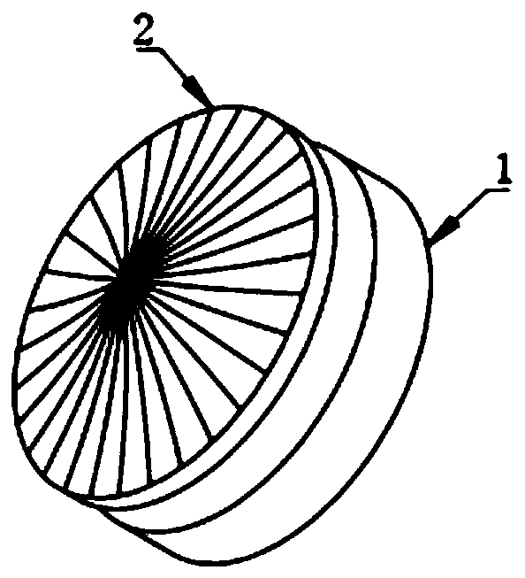
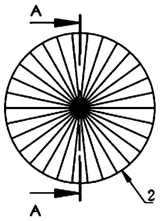
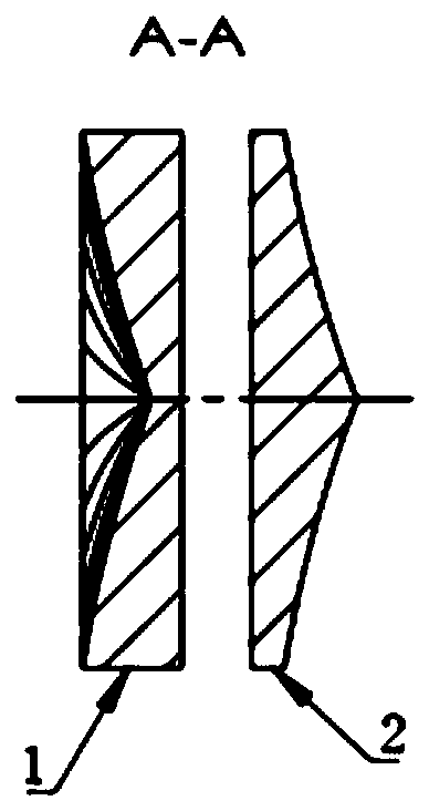
[0028] Figure 1-Figure 3 A microlens group for obtaining an adjustable annular beam is shown, including a plano-concave microlens 1 and a plano-convex microlens 2 .

[0029] In this solution, the central axis of the plano-concave microlens 1 and the plano-convex microlens 2 are coaxial, and the plano-concave microlens 1 or the plano-convex microlens 2 can rotate along the central axis;

[0030] The lens materials of the plano-concave microlens 1 and the plano-convex microlens 2 are fused silica materials;

[0031] The plano-concave microlens 1 and the plano-convex microlens 2 are based on the combination of axicon beam splitting and angular beam splitting, and are axisymmetric angular array microlenses;

[0032] The plano-concave microlens 1 and the plano-convex microlens 2 have the same angular beam splitting units, the number of which satisfies 10 to 100, and all the angular beam splitting units have the same beam splitting angle, and the beam splitting vertices converge i...


PUM


Abstract

The invention discloses a micro-lens group for obtaining an adjustable annular light beam. The micro-lens group comprises a plano-concave micro-lens and a plano-convex micro-lens, is novel in structural design. According to the micro-lens obtained based on combination of axicon light splitting and angular light splitting, under incidence of parallel or nearly parallel circular light beams, one micro-lens is rotated by a small angle along a light beam transmission axis, and a focusing lens is matched to obtain a focusing light beam, so that a solid light spot of a focusing focus is converted into an annular light spot, and the diameter of the annular light spot is continuously adjustable; while the spot diameter and the edge energy distribution are increased, the focal depth length of a focused light beam section can be greatly increased, the plate cutting speed, the section quality, the perpendicularity and the cutting thickness can be improved, and the method is particularly suitablefor medium and thick plate cutting application of a continuous fiber laser with the fiber core diameter of 50 microns or above.

Description

technical field [0001] The invention relates to the technical field of fiber laser cutting, in particular to a microlens group for obtaining an adjustable ring beam. Background technique [0002] Due to the advantages of high electro-optical conversion efficiency, good fiber flexibility, high coupling efficiency, and good beam quality, as well as the emergence of high-power lasers, fiber lasers have made their market share increasingly prominent. At present, fiber-coupled output lasers of kilowatt level are quite popular. Watt-level lasers are gradually released to the market, making fiber laser processing more and more common. [0003] The laser cutting application of fiber laser covers various metal processing markets such as stainless steel, carbon steel, aluminum, copper, etc. With the increase of laser power, the cutting thickness of plates of different materials becomes thicker. [0004] As we all know, although the conventional aberration-absorbing optical configurat...

Claims


Application Information

Patent Timeline
IPC IPC(8): G02B27/09G02B1/00G02B19/00B23K26/06B23K26/073
CPCB23K26/0648B23K26/0734G02B1/00G02B19/0014G02B27/0927G02B27/0955G02B27/0961
Inventor 邵华江李思佳
Owner SHANGHAI EMPOWER AUTOMATION TECH CO LTD
Learn More