Annealing device for copper wire processing

An annealing device and copper wire technology, which is applied in the field of copper wire processing, can solve the problems of affecting the quality of copper wire, reducing the service life, and having a small amount of spots, so as to achieve the effect of improving annealing quality and improving quality

Pending Publication Date: 2020-06-19
江西远桥电磁线科技协同创新有限公司
View PDF0 Cites 1 Cited by
  • Summary
  • Abstract
  • Description
  • Claims
  • Application Information

AI Technical Summary

Problems solved by technology

[0002] The existing copper wire annealing device is not equipped with a cleaning function. After annealing, a certain amount of emulsion will be produced on the surface of the copper wire. The emulsion is corrosive and will corrode the surface of the copper wire, resulting in rough surface and a small amount of spots on the surface of the copper wire. , affecting the quality of the copper wire and reducing its service life, there are deficiencies; and the existing annealing equipment is that the high-temperature copper wire directly enters the cooling liquid for annealing, and the high-temperature copper wire is quickly cooled to a low temperature, and the annealing effect is not good

Method used


Image

  • Annealing device for copper wire processing
  • Annealing device for copper wire processing
  • Annealing device for copper wire processing

Examples


Embodiment Construction

[0014] The following will clearly and completely describe the technical solutions in the embodiments of the present invention with reference to the accompanying drawings in the embodiments of the present invention. Obviously, the described embodiments are only some, not all, embodiments of the present invention. Based on the embodiments of the present invention, all other embodiments obtained by persons of ordinary skill in the art without making creative efforts belong to the protection scope of the present invention.

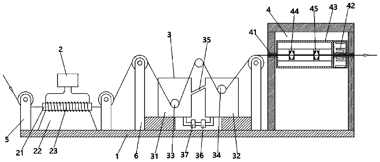
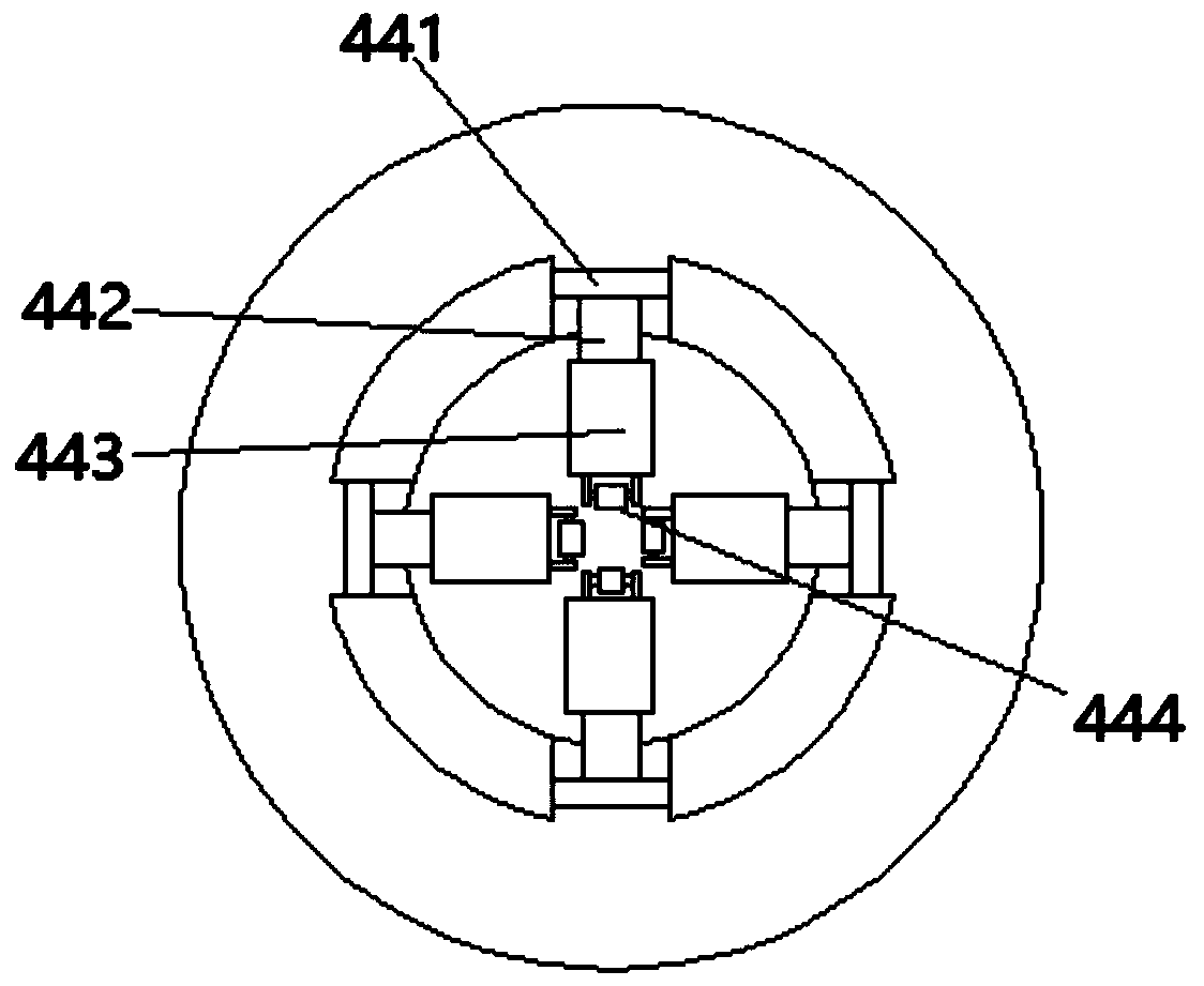
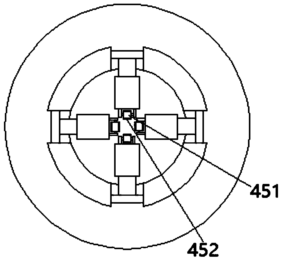
[0015] Such as Figure 1-3 As shown, an annealing device for copper wire processing includes a base 1, which is characterized in that: the base 1 is sequentially provided with a heat preservation mechanism 2, a cooling mechanism 3, and a cleaning mechanism 4 from left to right; the heat preservation mechanism No. 1 guide wheel 5 is provided on both sides of 2, and the No. 1 guide wheel 5 is fixedly welded on the base 1. The heat preservation mechanism 2 includ...


PUM


Abstract

The invention discloses an annealing device for copper wire processing. The annealing device comprises a base, wherein a heat preservation mechanism, a cooling mechanism, a cleaning mechanism, a firstguide wheel and a second guide wheel are arranged on the base; the heat preservation mechanism comprises heat preservation cotton, a heat preservation cotton base is arranged at the lower end of theheat preservation cotton, and an induction coil is wound around the heat preservation cotton; the cooling mechanism comprises first annealing grooves and second annealing grooves, wherein the first annealing grooves are provided with first fixed pulleys, the second annealing grooves are internally provided with second fixed pulleys, flow guide pipes are arranged between the first annealing groovesand the second annealing grooves, and a circulating water pump and a cooling device are arranged at the bottoms of the first annealing grooves and the bottoms of the second annealing grooves; and thetwo ends of the cleaning mechanism are connected with fixing shafts in an inserted mode, the outer side of the fixing shaft at the right end of the cleaning mechanism is provided with an outer rotormotor in a sleeved mode, the output end of the outer rotor motor is connected with a scrubbing pipe, and a first scrubbing device and a second scrubbing device are arranged in the scrubbing pipe. Theannealing device is simple in structure, high in annealing quality, and simple and convenient to operate due to the provision of a cleaning device.

Description

technical field [0001] The invention relates to the field of copper wire processing, in particular to an annealing device for copper wire processing. Background technique [0002] The existing copper wire annealing device is not equipped with a cleaning function. After annealing, a certain amount of emulsion will be produced on the surface of the copper wire. The emulsion is corrosive and will corrode the surface of the copper wire, resulting in rough surface and a small amount of spots on the surface of the copper wire. , affecting the quality of the copper wire and reducing its service life, there are deficiencies; and the existing annealing equipment is that the high-temperature copper wire directly enters the cooling liquid for annealing, and the high-temperature copper wire is quickly cooled to a low temperature, and the annealing effect is not good. Contents of the invention [0003] The object of the present invention is to provide an annealing device for copper wir...

Claims


Application Information

Patent Timeline
IPC IPC(8): C22F1/08C21D9/52
CPCC21D9/0062C21D9/525C22F1/002C22F1/08
Inventor 王贤良
Owner 江西远桥电磁线科技协同创新有限公司
Why Eureka
Try Eureka