


Quick Research
Generate reliable direction feasibility study reports for your R&D in just a few steps.

Technical Q&A
Discover and master advanced knowledge NOW. Basics, ideas, possibilities, all at once.

Find Solutions
As an expert in R&D theories, this can generate solutions to your technical problems instantly.

Evaluate Feasibility
Analyze your overall solution with one click, know your potential R&D risks in advance.

Monitor Landscape
Get weekly tech updates, stay abreast of the latest tech innovations and key insights.
Tail gas dehydration and dust removal tower for preparing sponge iron through gas-based reduction
A technology of sponge iron and dust removal tower, which is applied in the field of metallurgy, can solve the problems of impurity gas removal, incomplete removal of impurities, and influence on the quality of tail gas, etc., and achieve the effect of complete dust removal, small footprint, and saving equipment consumption
- Summary
- Abstract
- Description
- Claims
- Application Information
AI Technical Summary
Problems solved by technology
Method used
Image

Examples
Embodiment 1
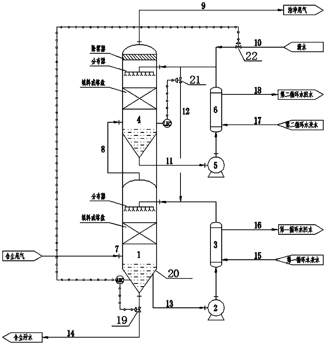
[0033] A tail gas dehydration and dedusting tower for preparing sponge iron by gas-based reduction, its structure is shown as follows figure 1 As shown, the cylindrical tower body part includes a pre-dust removal section 1 and a fine dust removal section 4 connected in sequence. Both dust removal sections include distributors, packing or trays, and conical sedimentation parts. An exhaust pipe is used between the two dust removal sections. 8 are connected, and the top of the fine dust removal section 4 is additionally provided with a mist eliminator, the tail gas enters the tail gas inlet 7 on the side wall of the pre-dust removal section, and passes through the pre-dust removal section 1, tail gas pipe 8, fine dust removal section 4 and the dedusting section successively in the tower body Fogger for dehydration and dust removal. Subsequent explanation of the water circulation part connected to the pre-dust removal section 1 and the fine dust removal section 4 respectively
[...
Embodiment 2
[0041] A tail gas dehydration and dust removal process for preparation of sponge iron by gas-based reduction, which utilizes the tail gas dehydration and dust removal tower of the embodiment, and the process is as follows:
[0042] The high-temperature dust-laden exhaust gas enters the pre-dust removal section 1 through the pipeline from the exhaust gas inlet 7 and fully cools and washes with the first-stage washing water therein. After cooling and washing, the dust in the exhaust gas is separated from the exhaust gas under the action of gravity and settles at the bottom of the first cone-shaped sedimentation part. , the tail gas enters the fine dust removal section 4 through the tail gas pipe 8 and continues to fully cool and wash with the secondary washing water therein, rises and passes through the demister above the fine dust removal section 4 to remove most of the droplets in the tail gas, and the purified tail gas passes through the tail gas The outlet is discharged into ...
PUM
| Property | Measurement | Unit |
|---|---|---|
| angle | aaaaa | aaaaa |
Abstract
Description
Claims
Application Information
 - R&D Engineer
- R&D Manager
- IP Professional
- Industry Leading Data Capabilities
- Powerful AI technology
- Patent DNA Extraction
Browse by: Latest US Patents, China's latest patents, Technical Efficacy Thesaurus, Application Domain, Technology Topic, Popular Technical Reports.
© 2024 PatSnap. All rights reserved.Legal|Privacy policy|Modern Slavery Act Transparency Statement|Sitemap|About US| Contact US: help@patsnap.com