
Low-temperature smoking set with lamplight display

A low-temperature, smoking device technology, applied in the direction of tobacco, smoker's products, applications, etc., can solve the problems of difficult smoking device charging time, dazzling lighting, affecting user experience, etc., to avoid reduced experience, soft brightness, and improved appearance. The effect of beauty

Pending Publication Date: 2020-06-19
CHINA TOBACCO HUNAN INDAL CORP
View PDF2 Cites 1 Cited by
  • Summary
  • Abstract
  • Description
  • Claims
  • Application Information

AI Technical Summary

Problems solved by technology

Under normal circumstances, when low-temperature smoking appliances are in use, the heating time of each cigarette is fixed (the system is pre-set). Generally, you can smoke more than a dozen cigarettes, and then you need to charge them. However, consumers usually don’t remember how many cigarettes they have smoked, so it is difficult for them to accurately grasp the charging time of smoking appliances.
[0004] The Chinese patent application number 201320635746.0 discloses an electronic cigarette with a power display device, and the Chinese patent application number 201420622436.X discloses a power supply device and an electronic cigarette. A number of LED lights or indicator lights of the battery can display the amount of battery power through the brightness of the LED lights or indicator lights. However, the way that the LED lights are directly projected on the outer surface of the smoking set is likely to cause glare and affect the user's experience.

Method used


Image

  • Low-temperature smoking set with lamplight display
  • Low-temperature smoking set with lamplight display
  • Low-temperature smoking set with lamplight display

Examples


Embodiment

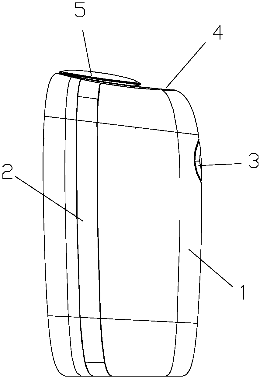
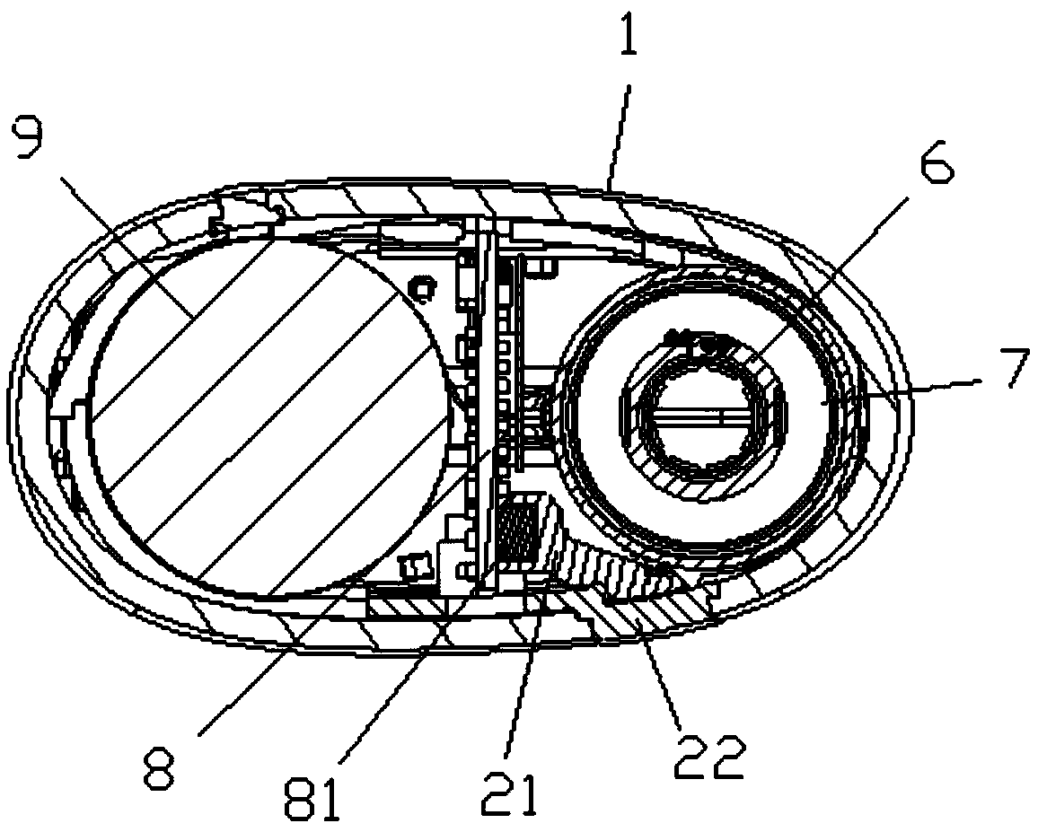
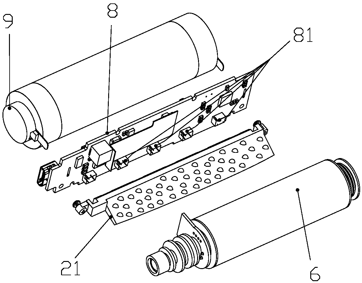
[0029] see figure 1 and figure 2 , the low-temperature smoking appliance shown in the figure is a preferred solution of the present invention, including a casing 1 and a light emitting unit 2 arranged on the casing 1 . The casing 1 is the entire body casing of the low-temperature smoking appliance. The casing 1 in this embodiment is divided into a front casing and a rear casing, which are buckled together to form a complete casing 1; the casing 1 is provided with a key switch 3, which 3. It is electrically connected with the PCB board 8 inside the shell 1. The PCB board 8 is used as the electronic control unit of the low-temperature smoking set to control the start-up and shutdown of the low-temperature smoking set; The cigarette is inserted from the cigarette insertion port 4 into the fixed heating element 6 inside the low-temperature smoking set. The heating element 6 is started and closed by the PCB board 8 and the key switch 3 together, and the inserted cigarette is heat...


PUM


Abstract

The present invention discloses a low-temperature smoking set with lamplight display. A light emitting unit is arranged on the low-temperature smoking set and comprises a plurality of light emitting sources electrically connected with an electric control unit of the low-temperature smoking set, and a light guide plate for transmitting light rays emitted by the light emitting sources to a specificdirection; one end surface of the light guide plate is close to luminous sources; the other end surface extends to a shell of the low-temperature smoking set; the two end surfaces are light transmitting faces, the side surface of the light guide plate is a light reflecting surface, a plurality of convex or concave light reflecting points are arranged on the light reflecting surface, and part or all of light emitted by the light emitting source is reflected by the light reflecting surface and the light reflecting points and propagates along the interior of the light guide plate and is displayedon the shell of the low-temperature smoking set in a continuous light band mode. The light-emitting unit can be used for displaying the electric quantity and the working state of the low-temperaturesmoking set, so that a user can visually know the battery use condition of the low-temperature smoking set or the use state of the electronic smoking set, and the light-emitting effect can be simply displayed, so that the appearance of the electronic smoking set is improved.

Description

technical field [0001] The invention belongs to the field of low-temperature smoking, and in particular relates to a low-temperature smoking set with light display. Background technique [0002] Traditional cigarettes need to be ignited and burned by an open flame to produce tobacco smoke. During the process of high temperature and pyrolysis, tobacco releases thousands of harmful mixed substances. Composition of substances, such as carbon monoxide, phenols, aldehydes, nicotine (nicotine), tobacco tar, etc., while heat-not-burn low-temperature smoking sets can effectively reduce the generation of harmful substances and be healthier. At present, the low-temperature smoking sets on the market mainly include two types of central heating and surrounding heating, both of which provide energy through the battery, supply the heating element to heat up, heat the low-temperature cigarettes to the set temperature, and generate smoke for the user to smoke. [0003] Most low-temperature...

Claims


Application Information

Patent Timeline
IPC IPC(8): A24F40/40
CPCA24F47/00
Inventor 刘建福钟科军郭小义黄炜尹新强易建华帅辉福邢立立
Owner CHINA TOBACCO HUNAN INDAL CORP
Learn More