
Stainless steel tube drilling machining device

A processing device, stainless steel tube technology, applied in positioning devices, boring/drilling, metal processing equipment, etc., can solve problems affecting product quality, tube wall compression deformation, drilling position deviation, etc., to improve processing production Efficiency, the effect of avoiding extrusion deformation

Inactive Publication Date: 2020-06-12
宋鹏
View PDF0 Cites 13 Cited by
  • Summary
  • Abstract
  • Description
  • Claims
  • Application Information

AI Technical Summary

Problems solved by technology

[0003] Some stainless steel pipes need to be drilled at the position of the pipe wall when they are in use, but the structure of the drilling processing device for stainless steel pipe fittings in the prior art is relatively simple, and usually the pipe fittings are drilled from the outside of the pipe fittings with a fixing device. However, when these fixing devices are fixed, if the fixing is too tight, the pipe wall may be deformed under pressure, and if the fixing force is small, the fixing stability of the pipe body may be insufficient, which may cause the pipe fittings to easily appear during the processing operation. The offset of the position will lead to the deviation of the drilling position, which will affect the actual product quality

Method used


Image

  • Stainless steel tube drilling machining device
  • Stainless steel tube drilling machining device
  • Stainless steel tube drilling machining device

Examples


Embodiment Construction

[0029] The following will clearly and completely describe the technical solutions in the embodiments of the present invention with reference to the accompanying drawings in the embodiments of the present invention. Obviously, the described embodiments are only some, not all, embodiments of the present invention. Based on the embodiments of the present invention, all other embodiments obtained by persons of ordinary skill in the art without making creative efforts belong to the protection scope of the present invention.

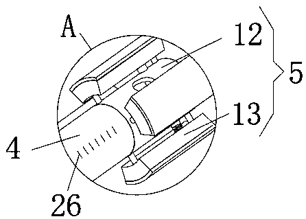
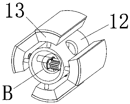
[0030] see Figure 1-10 , the present invention provides a technical solution: a stainless steel pipe drilling device, including a base 1 and a guide rail 2 arranged on the base 1, the base 1 is a rectangular flat plate, and the front end of the plate body is provided with a guide rail 2, the guide rail A slide 3 is provided above the slide 2. The slide 3 is a rectangular platform, which is slidably set on the guide rail 2 through the guide rail groove opened ...


PUM


Abstract

The invention discloses a stainless steel tube drilling machining device which comprises a base and a guide rail arranged on the base. The base is a rectangular slab. The guide rail is arranged at thefront end of the slab body. A sliding base is arranged above the guide rail. The sliding base is a rectangular platform and is slidably arranged on the guide rail through a guide rail groove formed in the lower surface. The sliding base is driven by a telescopic electric cylinder arranged at one end of the base, a supporting rod is fixedly welded to the upper surface of the sliding base, an innersupporting structure is arranged at the front end of the supporting rod, and a lower-position clamping base is arranged at the back side of the guide rail. Due to cooperative use of the inner supporting structure and an outer fixing structure, a steel tube to be drilled is internally supported through the interior of the steel tube. Compared with a traditional supporting structure for tube fixing, the phenomenon that due to excessively large exterior pressure, the tube to be fixed is extruded and deforms can be effectively avoided, and the phenomenon that due to excessively small clamping force, the tube offsets in the drilling process, and the drilling precision is affected can be effectively avoided.

Description

technical field [0001] The invention relates to the technical field related to the production and processing of stainless steel pipe fittings, in particular to a stainless steel pipe drilling and processing device. Background technique [0002] Stainless steel pipe is a hollow long round steel, mainly widely used in petroleum, chemical, medical, food, light industry, mechanical instruments and other industrial transportation steel pipes and mechanical structural components. In addition, when the bending and torsional strength are the same, the weight is lighter, so it is also widely used in the manufacture of mechanical parts and engineering structures. It is also commonly used as furniture and kitchen utensils. [0003] Some stainless steel pipes need to be drilled at the position of the pipe wall when they are in use, but the structure of the drilling processing device for stainless steel pipe fittings in the prior art is relatively simple, and usually the pipe fittings a...

Claims


Application Information

Patent Timeline
Patent Type & Authority Applications(China)
IPC IPC(8): B23Q3/06B23B41/00
CPCB23B41/00B23Q3/064
Inventor 宋鹏
Owner 宋鹏
Learn More