
Mounting and pouring process of prefabricated reinforced concrete inspection well

A technology of reinforced concrete and prefabricated assembly, which is applied in artificial islands, water conservancy projects, infrastructure projects, etc. It can solve the problems of inspection well safety, poor concrete waterproof effect, and loose concrete structure. It is not easy to achieve safety. Easy to fall off, not easy to crack

Inactive Publication Date: 2020-06-05
广州坚磊建设有限公司
View PDF2 Cites 1 Cited by
  • Summary
  • Abstract
  • Description
  • Claims
  • Application Information

AI Technical Summary

Problems solved by technology

[0004] The above-mentioned existing technical solutions have the following defects: because the inspection wells are usually placed underground, and there is usually groundwater underground, the groundwater will inevitably produce water vapor, and even some inspection wells are soaked in groundwater, while the existing The waterproof effect of the concrete used for pouring the inspection well is poor, so that the water vapor of the groundwater can easily penetrate into the concrete, making the structure of the concrete loose, which can easily affect the strength of the concrete, and even easily affect the safety of the inspection well , so there is still room for improvement

Method used


Image

  • Mounting and pouring process of prefabricated reinforced concrete inspection well
  • Mounting and pouring process of prefabricated reinforced concrete inspection well
  • Mounting and pouring process of prefabricated reinforced concrete inspection well

Examples

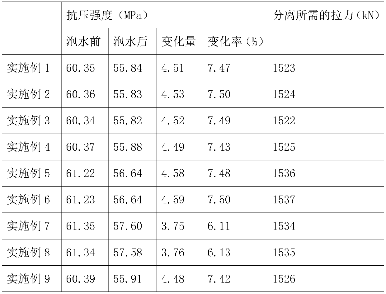
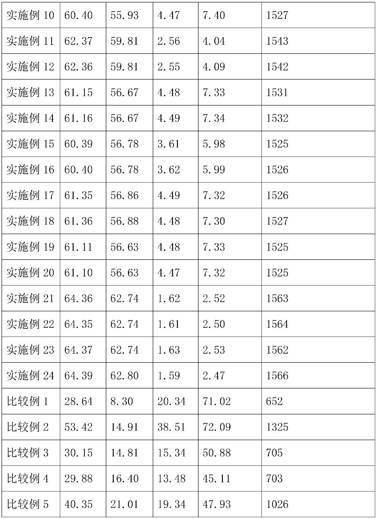

Embodiment 1

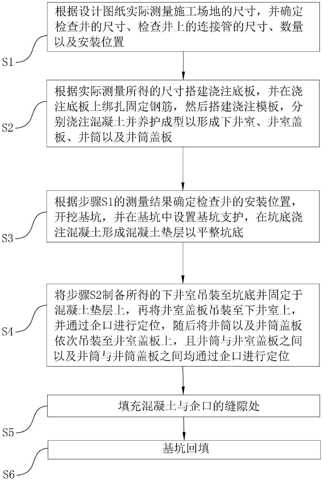
[0071] A prefabricated assembled reinforced concrete inspection well installation pouring process, comprising the following steps:

[0072] S1. Size measurement, as follows:

[0073] Measure the size of the construction site according to the design drawings, determine the size of the inspection well, the size, quantity and installation location of the connecting pipes on the inspection well, mark the installation location, and reserve the location for installing the connecting pipes.

[0074] S2. Inspection well prefabrication, details are as follows:

[0075] Build the pouring base plate according to the actual measured size, and tie and fix the steel bars on the pouring base plate, then build the pouring formwork, pour concrete respectively and cure and shape to form the lower well chamber, well chamber cover plate, well shaft and well shaft cover plate, and the curing temperature is controlled as follows: 45°C, the controlled curing time is 15 days.

[0076] Wherein, the ...

Embodiment 2

[0087] The difference with embodiment 1 is:

[0088] The consumption of each component that adds in the step S2 is as follows:

[0089] 15.5kg of water; 65kg of sand; 45kg of stone; 17.5kg of Portland cement; 3kg of paraffin; 2kg of zinc methacrylate; 1kg of casein; 0.3kg of chitin.

Embodiment 3

[0091] The difference with embodiment 1 is:

[0092] The consumption of each component that adds in the step S2 is as follows:

[0093] 13kg of water; 60kg of sand; 50kg of stone; 20kg of Portland cement; 4kg of paraffin; 1.5kg of zinc methacrylate; 0.75kg of casein; 0.2kg of chitin.


PUM

PropertyMeasurementUnit
particle diameteraaaaaaaaaa
particle size (mesh)aaaaaaaaaa

Abstract

The invention relates to the technical field of urban pipe network construction, in particular to a mounting and pouring process of a prefabricated reinforced concrete inspection well. The process comprises the following steps of S1, measuring the size; S2, prefabricating an inspection well; S3, excavating a foundation pit; S4, mounting a prefabricated inspection well; S5, sealing; and S6, backfilling the foundation pit, wherein the concrete for prefabricating the inspection well comprises the following components in parts by mass: 15-20 parts of Portland cement; 13-18 parts of water; 60-65 parts of sand; 45-50 parts of stone; 3-5 parts of paraffin; 1-2 parts of zinc methacrylate; 0.5-1 part of casein; 0.1 to 0.3 part of chitin. The mounting and pouring process disclosed by the invention has the effect that the compression strength of the inspection well is not easily influenced by underground water.

Description

technical field [0001] The invention relates to the technical field of urban pipe network construction, in particular to a prefabricated assembled reinforced concrete inspection well installation and pouring process. Background technique [0002] At present, in order to facilitate the installation and maintenance of power supply, water supply, drainage, sewage, communication, cable TV, gas pipes, street lamp lines, etc. of urban underground infrastructure, it is usually installed at the intersection, turning, pipe diameter or slope change, and Inspection wells are set at regular intervals on straight pipe sections. [0003] The existing prefabricated reinforced concrete inspection well installation method generally includes dimension measurement, pouring prefabrication of the inspection well, excavation of foundation pit and installation of the prefabricated well. [0004] The above-mentioned existing technical solutions have the following defects: because the inspection we...

Claims


Application Information

Patent Timeline
Patent Type & Authority Applications(China)
IPC IPC(8): E02D29/12E02D15/02C04B28/04C04B111/27
CPCC04B28/04C04B2111/00293C04B2111/27C04B2201/50E02D15/02E02D29/12E02D29/125C04B24/36C04B24/04C04B24/14C04B24/38C04B14/06C04B14/02
Inventor 孙敏强黄磊栋邝泳斌李智滔朱志斌邓志光
Owner 广州坚磊建设有限公司
Learn More