
Ultrasonic CT sound velocity imaging method based on deep residual network

An imaging method and residual technology, applied in the analysis of solids using sonic/ultrasonic/infrasonic waves, material analysis using sonic/ultrasonic/infrasonic waves, neural learning methods, etc., to achieve improved accuracy, strong anti-noise ability, and strong fitting ability Effect

Pending Publication Date: 2020-06-02
苏州二向箔科技有限公司
View PDF0 Cites 2 Cited by
  • Summary
  • Abstract
  • Description
  • Claims
  • Application Information

AI Technical Summary

Problems solved by technology

[0004] The purpose of the present invention is to provide an ultrasonic CT sound velocity imaging method based on a deep residual network to solve the problem of how to implement the end-to-end method proposed in the above background technology, and to avoid the cumbersome adjustment of the number of iterations and regularization parameters in some traditional methods. steps and make the reconstruction method more robust against noise and obtain higher accuracy

Method used


Image

  • Ultrasonic CT sound velocity imaging method based on deep residual network
  • Ultrasonic CT sound velocity imaging method based on deep residual network
  • Ultrasonic CT sound velocity imaging method based on deep residual network

Examples


Embodiment Construction

[0029] The following will clearly and completely describe the technical solutions in the embodiments of the present invention with reference to the accompanying drawings in the embodiments of the present invention. Obviously, the described embodiments are only some, not all, embodiments of the present invention. Based on the embodiments of the present invention, all other embodiments obtained by persons of ordinary skill in the art without making creative efforts belong to the protection scope of the present invention.

[0030] In the description of the present invention, it should be noted that the orientations or positional relationships indicated by the terms "upper", "lower", "inner", "outer", "top / bottom" etc. are based on the orientations shown in the drawings Or positional relationship is only for the convenience of describing the present invention and simplifying the description, but does not indicate or imply that the device or element referred to must have a specific ...


PUM


Abstract

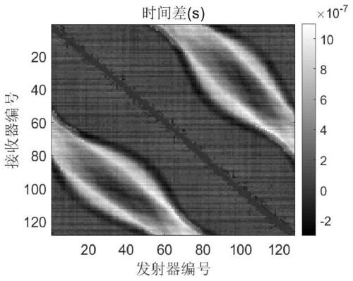
The invention belongs to the technical field of ultrasonic tomography in biomedical hyper-acoustics, and in particular to an ultrasonic CT sound velocity imaging method based on a deep residual network. The ultrasonic CT sound velocity imaging method based on the deep residual network comprises the following steps that S1, immersing a target detection object into a water tank provided with an annular ultrasonic transducer, S2, extracting signal first arrival points in two sets of original ultrasonic data respectively, corresponding subtraction is conducted, and a transit time difference graphis obtained; S3, constructing a deep residual error network model; s4, making training data and labels and inputting the training data and the labels into the network; training a model, according to the method, the projection data acquired by the acquisition equipment is reconstructed by utilizing the deep residual network in deep learning, so that the precision of a reconstruction result is improved, and the tedious steps of multiple iterations, regularization parameter adjustment and the like are avoided.

Description

technical field [0001] The invention relates to the technical field of ultrasonic tomographic imaging in biomedical ultrasonics, in particular to an ultrasonic CT sound velocity imaging method based on a deep residual network. Background technique [0002] Breast cancer has become the cancer with the highest incidence among women in the world, and its incidence is still showing an upward trend, so effective screening and diagnosis are very important. Ultrasonic CT sound velocity imaging technology has shown great advantages in the early diagnosis of breast cancer due to its advantages of non-radiation, low cost, and the ability to generate quantitative three-dimensional images. This technology uses a ring-shaped ultrasonic transducer array as a measuring device, and detects the structure of the target object by transmitting and receiving ultrasonic waves between the transducers, and uses the information contained in the ultrasonic signals received by the transducers. Ultras...

Claims


Application Information

Patent Timeline
IPC IPC(8): G06T11/00G06N3/04G06N3/08G01N29/06G01N29/44
CPCG06T11/003G06N3/084G01N29/0654G01N29/44G06N3/045
Inventor 屈晓磊
Owner 苏州二向箔科技有限公司
Learn More