Glass rod cutting device

A technology for cutting devices and glass rods, applied in glass cutting devices, glass manufacturing equipment, manufacturing tools, etc., can solve problems such as errors, waste of raw materials, and low efficiency, and achieve the effects of ensuring cutting length, ensuring high efficiency, and avoiding wear

Inactive Publication Date: 2020-05-22
HUBEI PAIRUISI OPTICAL GLASS TECH CO LTD
View PDF0 Cites 0 Cited by
  • Summary
  • Abstract
  • Description
  • Claims
  • Application Information

AI Technical Summary

Problems solved by technology

The existing glass rod cutting device has the following problems: 1) Due to errors in manual feeding, and the principle of adhering to the principle that more blanks should not be less, usually the cut blanks are longer, which leads to waste of raw materials, and because the remaining blanks Too much, which increases the difficulty of later grinding; 2), one piece of equipment completes the cutting of one bar at a time by one employee, which leads to low efficiency; 3), the glass rod generates high heat during the cutting process, which is easy to damage the glass surface

Method used


Image

  • Glass rod cutting device
  • Glass rod cutting device
  • Glass rod cutting device

Examples


Embodiment Construction

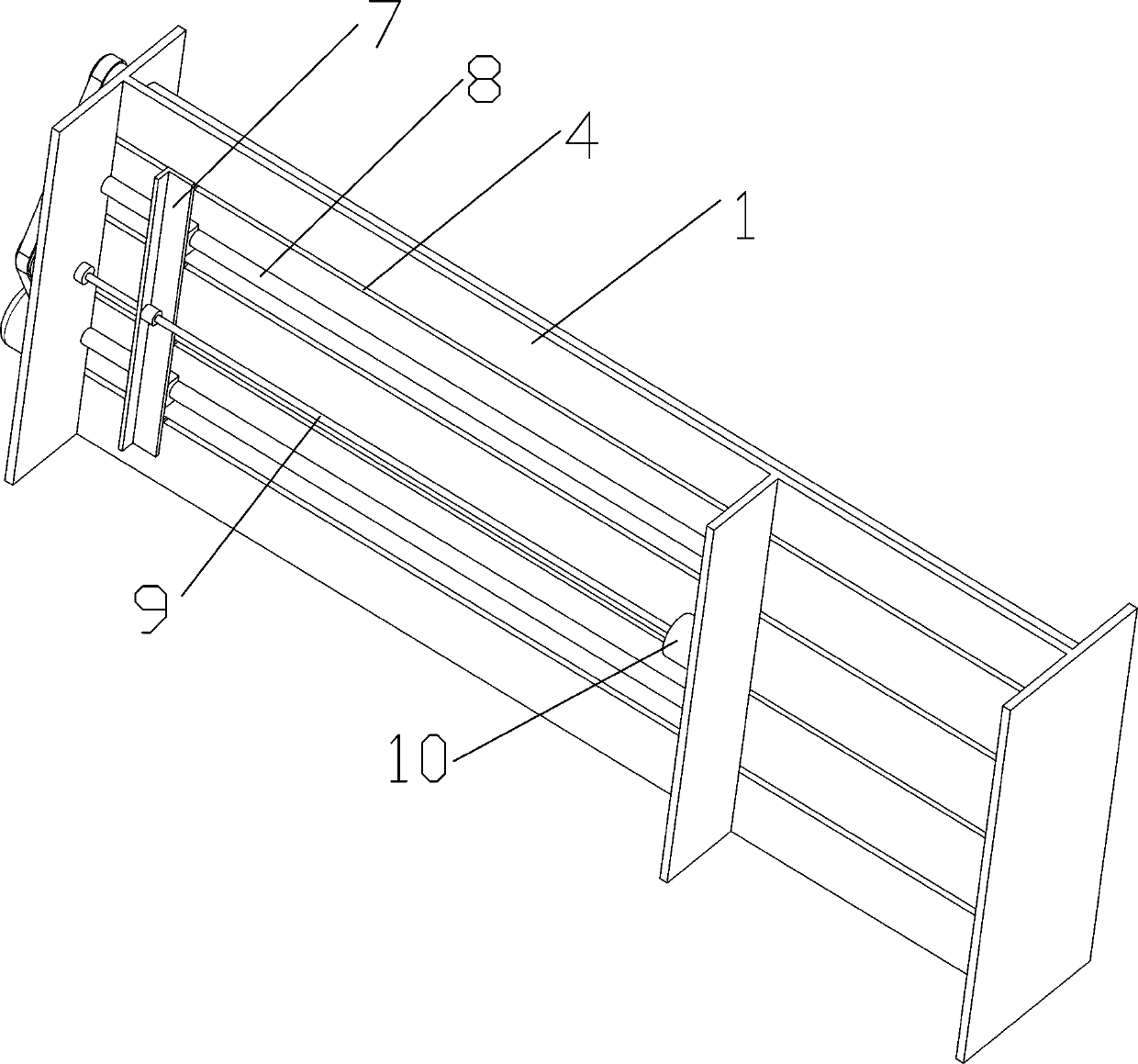
[0027] A glass rod cutting device, comprising a glass rod cutting and conveying platform, and a lifting and cutting device;

[0028] Specifically, such as Figure 1-6 As shown, the glass rod cutting and conveying platform includes a platform 1, and the platform 1 includes a front and rear base, and a horizontal support plate is provided between the front and rear bases, and four slots 4 are arranged at intervals along the length direction on the support plate. Correspondingly, there are four sets of rotating rollers 2 above the support plate, and the two ends of the rotating rollers 2 are rotatably connected to the base through bearings. There are gaps reserved between the groups of rotating rollers 2, and the gaps are aligned with the grooves 4 on the supporting plate. right. The push rod 5 is located above the gap of the roller 2, and the lower end is connected with the slide plate 7 through the connecting rod 6, and the slide plate 7 is located below the platform 1. Slidi...


PUM


Abstract

The invention relates to a glass rod cutting device, which comprises a glass rod cutting conveying platform and a lifting cutting device, wherein the glass rod cutting conveying platform comprises a platform body, plural sets of paired rotating rollers are arranged on the platform body, the paired rotating rollers are driven by a transmission mechanism to rotate in the same direction, a gap is reserved between each set of the paired rotating rollers, the gaps are right opposite to grooves in the platform body, ejection rods are located above the gaps of the rotating rollers, the lower ends ofthe ejection rods are connected with a pushing mechanism, the lifting cutting device comprises a support seat fixed to the upper end of the platform body, a lifting air cylinder is installed at the top end of the support seat, the piston rod of the lifting air cylinder is connected with the cutting mechanism, and the two ends of the cutting mechanism are slidably arranged on lifting sliding railson the side wall of the support seat. According to the glass rod cutting device provided by the invention, the cutting conveying platform and the lifting cutting device are arranged, so that the working efficiency can be improved.

Description

technical field [0001] The invention relates to glass lens processing and production equipment, in particular to a glass rod cutting device. Background technique [0002] In the production process of glass lenses, the first process is to cut the glass rod into sections, and then perform subsequent softening and hot pressing. The existing glass rod cutting device has the following problems: 1) Due to errors in manual feeding, and the principle of adhering to the principle that more blanks should not be less, usually the cut blanks are longer, which leads to waste of raw materials, and because the remaining blanks Too much, which increases the difficulty of later grinding; 2), one piece of equipment completes the cutting of one bar at a time by one employee, which leads to low efficiency; 3), the glass rod generates high heat during the cutting process, which is easy to damage the glass surface. Contents of the invention [0003] The technical problem to be solved by the p...

Claims


Application Information

Patent Timeline
Patent Type & Authority Applications(China)
IPC IPC(8): C03B33/06
CPCC03B33/06
Inventor 胡耿政
Owner HUBEI PAIRUISI OPTICAL GLASS TECH CO LTD
Why Eureka
Try Eureka