
Optical tweezer system based on vortex pair light beams

A beam-shrinking system and vortex technology, applied in the field of optics, can solve the problems of difficult control of rod-shaped particles, inability to control the relative position of two particles, and inability to rotate the particles in a directional manner, achieving rich application objects, adjustable rotation speed, and convenient operation. Effect

Active Publication Date: 2020-05-19
ZHEJIANG UNIV
View PDF12 Cites 5 Cited by
  • Summary
  • Abstract
  • Description
  • Claims
  • Application Information

AI Technical Summary

Problems solved by technology

[0007] The present invention aims to solve the problems in the prior art that the relative position control of double particles cannot be realized, and the directional rotation of particles with special structures such as strips cannot be realized, and provides an optical tweezers system based on vortex pairing beams
The optical tweezers system can realize the precise control and positioning of the relative position of two spherical particles in the plane, and the arbitrary controllable rotation operation of the rod-shaped particles in the plane, which makes the application objects of the optical tweezers system more abundant and effectively solves the existing problems. Difficult control of rod-shaped particles by optical tweezers

Method used


Image

  • Optical tweezer system based on vortex pair light beams
  • Optical tweezer system based on vortex pair light beams
  • Optical tweezer system based on vortex pair light beams

Examples


Embodiment 1

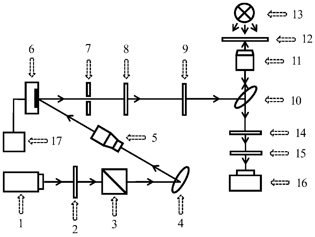
[0060] The laser 1 emits a linearly polarized light beam with a wavelength of 533 nm. After passing through the half-wave plate 2 and the polarization beam splitting prism 3, the polarization direction of the light is horizontal polarization, and the half-wave plate 2 is rotated to adjust the light intensity for capturing particles. The light beam enters the beam expander system 3 through the total mirror 4 to change the light propagation direction. The beam expander system 3 expands the light beam by a factor of two, and the diameter of the expanded beam is about 3mm, which can cover the liquid crystal panel of the spatial light modulator 6.

[0061] The light beam expanded by the beam expander system 3 is incident on the spatial light modulator 6, and the spatial light modulator 6 is controlled by the computer 17, and the vortex phase diagram is loaded in real time. The vortex pair beam modulated by the spatial light modulator 6 selects the first-order diffracted beam through th...

Embodiment 2

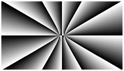
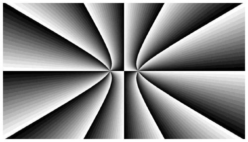
[0070] Using the same optical tweezers system as in Example 1, the vortex versus phase diagram loaded by the spatial light modulator is calculated by formula (1):

[0071]

[0072] Among them, φ represents the phase, m 1 ,m 2 It is any two equal integers, called the topological charge; a represents the off-axis distance of the double vortex phase singular point, which is any real number; u represents the abscissa; v represents the ordinate; i represents the imaginary unit.

[0073] The abscissa and ordinate of the vortex pair phase diagram are calculated according to formula (2):

[0074]

[0075] Among them, u represents the abscissa; v represents the ordinate; u 0 Represents the initial abscissa; v 0 Represents the initial ordinate; θ represents the rotation angle, which is a function of time; t represents the time parameter.

[0076] Take m 1 = 6, m 2 =6, a=0.9mm, the phase diagram of θ(t)=0° is used as the initial phase diagram, and the effect of capturing rod-shaped particles by t...


PUM


Abstract

The invention relates to the technical field of optics. The invention concretely relates to an optical tweezer system based on vortex pair light beams. The system comprises a laser, a collimation andbeam expansion system, a spatial light modulator, a confocal beam shrinkage system, a sample table and an observation unit which are arranged according to a light path, the spatial light modulator continuously loads different vortex pair light beam phase diagrams in real time, and a single vortex pair light beam is used for controlling and rotating particles in real time. According to the opticaltweezer system, the accurate regulation and positioning of two particles at any position in a plane and any controllable rotation operation in a rod-shaped particle plane can be realized, so that theapplication objects of the optical tweezer system are more abundant, and the problems that an existing optical tweezer system is difficult to control rod-shaped particles and accurately and directionally rotate are effectively solved.

Description

Technical field [0001] The present invention relates to the field of optical technology, in particular to an optical tweezers system based on vortex pairing of light beams. Background technique [0002] Optical tweezers technology is a technology that uses a strong focused laser beam as a light source. When the laser is irradiated on the particles, the laser will generate radiation force acting on the particles, thereby capturing and manipulating the particles. The principle is relatively simple, that is, a laser beam is highly focused as the light source of the optical tweezers, and the focused beam will trap the particles through the formed potential well, and the particles can also be manipulated to achieve rotation and other operations. Compared with many micromanipulation techniques, such as atomic force microscope, scanning probe microscope, etc., the advantages of optical tweezers are still very prominent. In particular, optical tweezers do not need to contact the particl...

Claims


Application Information

Patent Timeline
Patent Type & Authority Applications(China)
IPC IPC(8): G02B27/00G21K1/00
CPCG02B27/00G21K1/006G02B21/32G02B21/06G02B21/36G02B21/0088G02B26/06G02B26/02
Inventor 王立刚温积森高斌杰
Owner ZHEJIANG UNIV
Learn More