Laser directional energy deposition area calculation method of full convolutional neural network

A convolutional neural network and energy deposition technology, applied in the field of laser directional energy deposition area calculation, can solve problems such as unfavorable practical application of additive manufacturing products, affecting product mechanical properties, affecting product mechanical properties, etc., to reduce memory overhead, The effect of reducing the occurrence rate of defects and expanding the scope

Pending Publication Date: 2021-06-15
湖南珞佳智能科技有限公司
View PDF0 Cites 0 Cited by
  • Summary
  • Abstract
  • Description
  • Claims
  • Application Information

AI Technical Summary

Problems solved by technology

When using selective laser melting (SLM) technology, due to some physical processes in the manufacturing process, it is easy to produce defects such as spheroidization, pores, cracks, etc., which affect the mechanical properties of the product
When laser metal direct forming (LMDF) technology is used, along with the long-term periodic heating of the laser beam, local repeated heating and cooling, the rapid solidification and shrinkage of the molten pool under the strong confinement of the bottom of the pool and its associated short-term Non-equilibrium cyclic solid state phase transition can easily lead to severe deformation and cracking of parts, which seriously affects the mechanical properties of products
[0004] Factors such as these are extremely unfavorable for the practical application of additive manufacturing products in aerospace, medical and health fields that have extremely high requirements for product quality.

Method used


Image

  • Laser directional energy deposition area calculation method of full convolutional neural network
  • Laser directional energy deposition area calculation method of full convolutional neural network
  • Laser directional energy deposition area calculation method of full convolutional neural network

Examples


Embodiment Construction

[0053] The following will clearly and completely describe the technical solutions in the embodiments of the present invention with reference to the accompanying drawings in the embodiments of the present invention. Obviously, the described embodiments are only some, not all, embodiments of the present invention. Based on the embodiments of the present invention, all other embodiments obtained by persons of ordinary skill in the art without making creative efforts belong to the protection scope of the present invention.

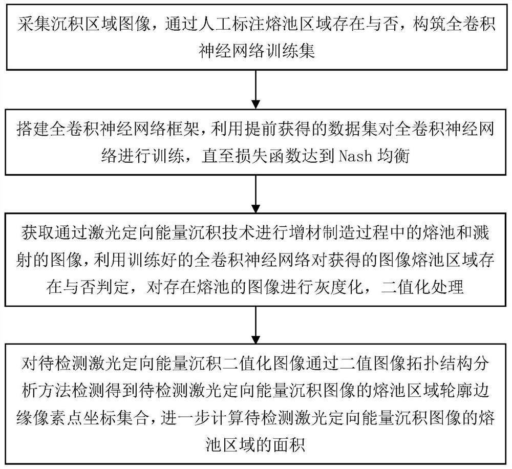
[0054] Combine below Figure 1 to Figure 5 The specific embodiment of the present invention is introduced as a method for calculating the laser directed energy deposition area of ​​a fully convolutional neural network, such as figure 1 As shown in the flow chart, it specifically includes the following steps:

[0055] Step 1: Collect multiple laser directed energy deposition area images, label each laser directed energy deposition area image with the melting p...


PUM


Abstract

The invention provides a laser directional energy deposition area calculation method of a full convolutional neural network. The method comprises the following steps: collecting a plurality of laser directional energy deposition area images, manually marking a molten pool label of each image, and further constructing a training set; building a full convolutional neural network, inputting the images in the training set into the neural network, predicting the existence value of the molten pool, further combining with the marked construction loss function, optimizing to Nash equilibrium, and obtaining an optimized neural network; collecting a to-be-detected image, inputting the to-be-detected image into the optimized neural network, and judging whether the image has a molten pool area; if the molten pool exists, graying the image to obtain a grey-scale image, and then carrying out binarization to obtain a binary image; and performing a topological structure analysis method on the binary image to obtain a molten pool contour pixel coordinate set of the image, and further calculating the area of the molten pool. According to the invention, the molten pool in the laser directional energy deposition process can be recognized, the area of the molten pool is calculated, and the manufacturing process can be regulated and controlled easily.

Description

technical field [0001] The invention belongs to the technical field of metal additive manufacturing detection, and in particular relates to a method for calculating the laser directed energy deposition area of ​​a fully convolutional neural network. Background technique [0002] Compared with the original additive manufacturing technology using photosensitive resin as raw material and using photocuring technology, the additive manufacturing technology using metal as raw material has better performance under the high requirements of the industrial field, and has been obtained in recent years. increasingly widespread attention. For parts with complex internal structures, additive manufacturing can greatly shorten the processing time compared with the traditional manufacturing mode of mechanical processing; for modern Internet-based high-frequency iterative product updates, since additive manufacturing can directly Realize the leap from 3D CAD files to real objects, and cooper...

Claims


Application Information

Patent Timeline
IPC IPC(8): G06T7/00G06T7/13G06T7/62G06T5/00G06N3/04G06N3/08
CPCG06T7/0004G06T7/13G06T7/62G06N3/08G06T2207/20081G06T2207/20084G06T2207/30164G06N3/045G06T5/90Y02P10/25
Inventor 李辉米纪千申胜男李正雄刘胜
Owner 湖南珞佳智能科技有限公司
Why Eureka
Try Eureka