Air intake and exhaust device for pipe

An exhaust device and effective technology, applied in the field of technical solar cells, can solve problems such as lateral air flow disturbance, adverse effects of square resistance uniformity, air flow disturbance, etc., and achieve the effect of uniform deposition reaction and stability

Pending Publication Date: 2020-05-19
帝尔激光科技(无锡)有限公司
View PDF0 Cites 0 Cited by
  • Summary
  • Abstract
  • Description
  • Claims
  • Application Information

AI Technical Summary

Problems solved by technology

[0003] The traditional high-temperature diffusion pipe simply adopts methods such as furnace inlet air inlet, furnace tail air extraction, furnace tail air inlet furnace inlet air extraction, or spraying air inlet furnace air extraction. The air inlet and exhaust pipes are all single-layer pipes. With this type of design, the direction of air intake or exhaust airflow is perpendicular to the silicon wafer and placed in the furnace tube, and a horizontal airflow will be generated in the furnace during the diffusion process. , causing airflow disturbance
In this case, the uneven distribution of doping gas reaction on the surface of the silicon wafer will adversely affect the uniformity of the square resistance in the entire furnace tube and between the wafers, and will also affect the thickness and doping of phosphosilicate glass or borosilicate glass on the surface of the silicon wafer. The distribution uniformity of the impurity concentration will affect the rear resistance of the laser SE in the next step.
[0004] In addition, there are other problems in the traditional high-temperature diffusion pipe, which are manifested as (1) only focus on the intake pipe, while the exhaust pipe is still a single-layer pipe, but this method will also cause lateral airflow disturbance; (2) the above-mentioned single-layer The intake pipe cannot mix the dopant gas evenly, which affects the uniform distribution of the diffused gas; (3) The irregular opening of the intake pipe leads to the incompatibility of the intake pipe and exhaust pipe, resulting in an increase in cost

Method used


Image

  • Air intake and exhaust device for pipe
  • Air intake and exhaust device for pipe
  • Air intake and exhaust device for pipe

Examples


Embodiment Construction

[0025] In order to make the object, technical solution and advantages of the present invention clearer, the present invention will be further described in detail below in conjunction with the accompanying drawings and embodiments. It should be understood that the specific embodiments described here are only used to explain the present invention, not to limit the present invention.

[0026] Below in conjunction with the accompanying drawings, the pipe intake and exhaust device for protection claimed by the present invention will be described in detail by taking it as an example.

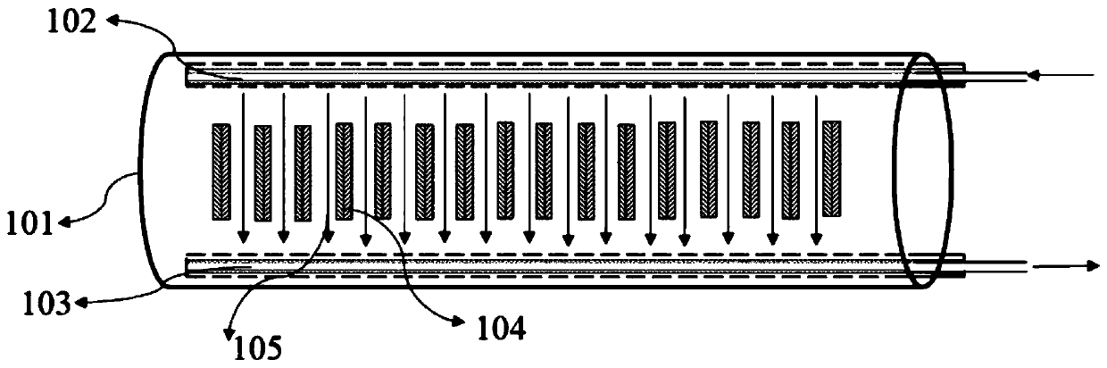
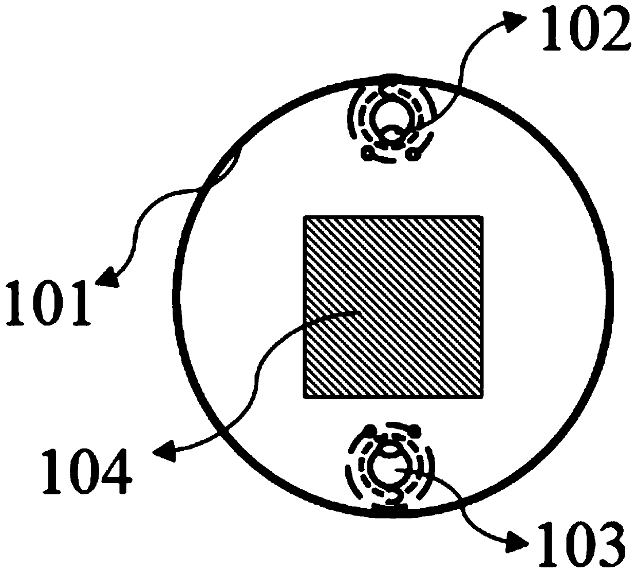
[0027] Such as figure 1 with figure 2 The shown air intake and exhaust device for pipes includes an air intake pipe 102 and an exhaust pipe 103, the air intake pipe 102 and the exhaust pipe 103 are distributed in the furnace pipe 101 and are close to the inner wall of the furnace, the air intake pipe 102 and the exhaust pipe 103 The silicon chips 104 arranged inside the furnace tube 101 are symmetr...


PUM


Abstract

The invention relates to an air intake and exhaust device for a pipe, which comprises an air intake pipe and an air exhaust pipe. The air intake pipe and the air exhaust pipe are distributed in a furnace pipe and are close to the inner wall of the furnace, and the air intake pipe and the air exhaust pipe are symmetrically distributed by taking a silicon wafer arranged in the furnace pipe as a center. The air inlet pipe and the air outlet pipe are both of a same multi-layer sleeve structure, and the multi-layer sleeve structure is formed by coaxially sleeving at least two air pipes from insideto outside. A plurality of air holes are formed in each layer of air pipe. The gas inlet pipe and the gas outlet pipe are of a multi-layer sleeve structure, and diffusion source gas and reaction residual waste gas can be fully and evenly mixed in the multi-layer sleeve structure and then enter or be discharged out of the furnace pipe through the inner space of the multi-layer sleeve structure. Onthe other hand, the positions, angles, hole diameters, hole distances and hole directions of the air holes in all the layers of air pipes can be adjusted, and therefore, the stability and uniformity of the direction of airflow entering the furnace pipe are achieved.

Description

technical field [0001] The invention relates to the technical field of solar cells, in particular to a pipe intake and exhaust device suitable for high-temperature diffusion pipes. Background technique [0002] At present, PERC+SE technology is one of the most mature high-efficiency battery technology routes, and has achieved mass production, in which diffusion is one of the core processes of laser selective emitter (SE) technology. Laser SE technology utilizes the dopant source in phosphosilicate glass or borosilicate glass deposited on the surface of the silicon wafer, and realizes the redistribution of the dopant source under the action of laser thermal effect. At present, the diffusion of crystalline silicon cells adopts the tubular diffusion method, and the uniformity of the diffusion is adjusted by adjusting the three factors of process time, gas flow rate and temperature. [0003] The traditional high-temperature diffusion pipe simply adopts methods such as furnace i...

Claims


Application Information

Patent Timeline
IPC IPC(8): C30B31/16C30B29/06H01L31/18
CPCC30B31/16C30B29/06H01L31/1804Y02P70/50
Inventor 张松朱俊陆红艳程晓伟朱凡李志刚
Owner 帝尔激光科技(无锡)有限公司
Why Eureka
Try Eureka