Coal ash slag cooling and dischargging system

A technology for cooling exhaust and coal ash, which is applied in the direction of gasification process, petroleum industry, and manufacture of combustible gas, etc. It can solve the problems of increasing equipment and raw coal input costs, clogging of circulating pumps and heat exchangers, and high overall height of slag discharge equipment, etc. problems, to achieve the effect of promoting the reaction of carbon and water vapor, reducing input costs, and increasing the content of effective gas components

Pending Publication Date: 2020-05-15
XINNENG ENERGY CO LTD
View PDF0 Cites 1 Cited by
  • Summary
  • Abstract
  • Description
  • Claims
  • Application Information

AI Technical Summary

Problems solved by technology

[0003] The above-mentioned slag discharge device has the following problems during use: 1. The ash needs to be cooled in the quenching chamber for a period of time, and the slag is continuously fed into the quenching chamber. The pump is forced to circulate, and the cooling water will contain some ash, which will cause blockage of the circulating pump and heat exchanger during the circulating cooling process, which will interrupt the work of the slag discharge device and affect the slag discharge efficiency; 2. Ash in the slag discharge tank Falling into the slag storage device by its own weight, the slag storage device can only be placed under the slag discharge tank, the location of the equipment is limited, the overall height of the slag discharge equipment is high, and it is not easy to repair and maintain; 3. Steam is introduced into the slag discharge channel Controlling the speed of slag discharge increases the amount of steam used, and steam needs to be produced by steam boilers, which increases the input cost of equipment and raw coal; 4. Pass cooling water into the slag discharge channel to cool the ash, and the slag cannot be completely submerged Cooling water, poor cooling effect

Method used


Image

  • Coal ash slag cooling and dischargging system
  • Coal ash slag cooling and dischargging system
  • Coal ash slag cooling and dischargging system

Examples


Embodiment 1

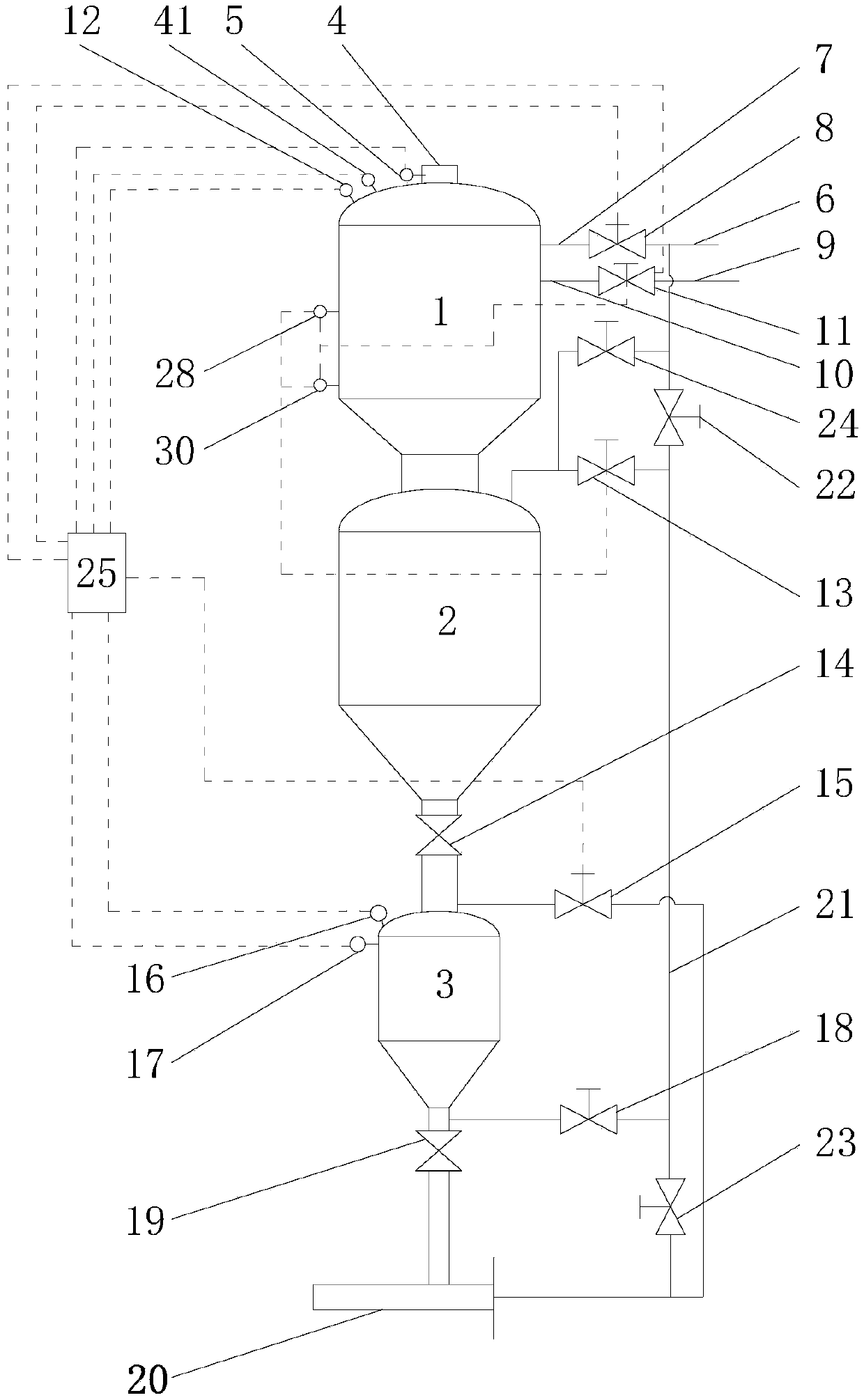
[0023] Such as Figure 1-3 As shown, a coal ash cooling slag discharge system includes a cold slag tank 1, a slag collection tank 2 and a slag discharge tank 3,

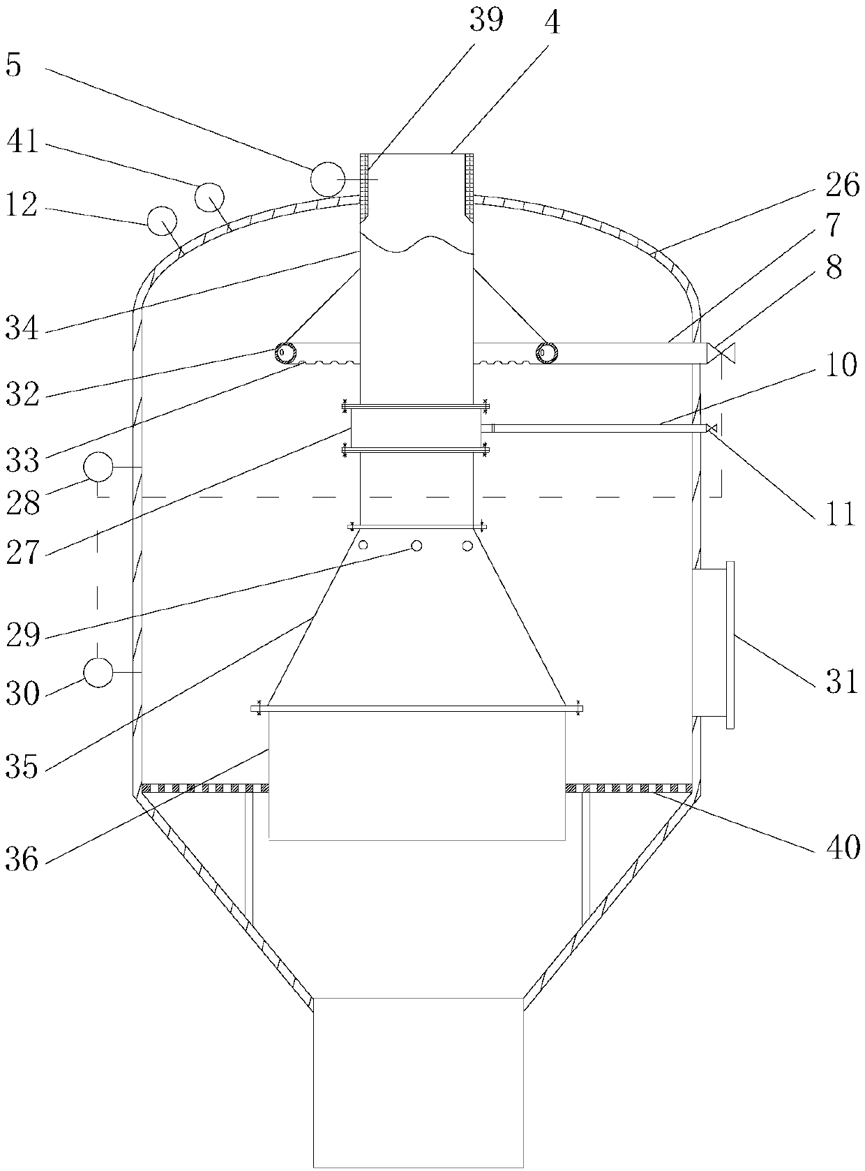
[0024] The cold slag tank 1 includes a tank body 26, and an ash and slag pipe 4 is vertically arranged in the middle of the tank body 26. The top of the ash slag pipe 4 extends to the outside of the top of the tank body 26, and the outlet of the ash slag pipe 4 extends to the cold slag tank. 1, a passage is formed between the bottom end of the ash pipe 4 and the bottom end of the tank body 26, and the ash slag falls into the tank body 26 through the ash pipe 4 for cooling.

[0025] The ash pipe 4 comprises a straight pipe heat exchange section 34, a diameter-expanding pipe vaporization section 35 and a straight pipe slag discharge section 36 connected successively from top to bottom. The diameter of the heat exchange section 34 of the tube can limit the diffusion of high-temperature ash in the cooling water, and can...

Embodiment 2

[0046] A kind of coal ash cooling and slagging method carried out by utilizing a kind of coal ash cooling and slag discharging system in embodiment 1, it comprises the following steps: (1) primary cooling of cooling gas, (2) secondary cooling of steam, (3) ) cooling water for three times cooling, (4) slag feeding and slag discharge of the slag discharge tank; wherein,

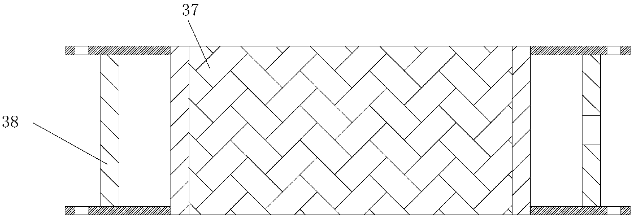
[0047] (1) Primary cooling of the cooling gas: the 850°C-900°C ash discharged from the fluidized bed gasification furnace enters the ash pipe 4, and the cooling gas carbon dioxide enters the pipe body 38 of the gas distribution pipe 27 through the gas filling pipe 10, and then passes through the sintering The metal filter element 37 sprays out evenly to cool the ash in the ash pipe 4 once. The ash cooled to 450°C-550°C moves down along the ash pipe 4, and the carbon dioxide after heat exchange with the ash flows along the ash pipe. Pipe 4 moves upwards into the fluidized bed gasifier; carbon dioxide is used ins...


PUM


Abstract

The invention discloses a coal ash slag cooling and discharging system. The system comprises a slag cooling tank, a slag collecting tank and a slag discharging tank, the outlet of an ash slag pipe extends to the inner bottom of the slag cooling tank, an ash slag temperature sensor is arranged in the top end of the ash slag pipe, a cooling water pipe is communicated with the water inlet pipe of theslag cooling tank, the water inlet pipe is provided with a water inlet control valve, the upper part of the ash slag pipe in the slag cooling tank is communicated with an inflating pipe, a cooling air pipe is communicated with the inflating pipe, the inflating pipe is provided with an inflating control valve, and the top of the slag cooling tank is provided with a slag cooling tank pressure sensor and a slag cooling tank temperature sensor. The system has the following advantages: carbon dioxide is introduced into the ash slag pipe to replace steam to control the slag discharging speed, and the ash slag is cooled primarily, so the use amount of steam is reduced, and the investment cost of a steam manufacturing device and raw material coal is reduced; and after the carbon dioxide enters afluidized bed gasifier, carbon dioxide generated by a reaction of carbon and oxygen in the fluidized bed gasifier can be inhibited, and carbon and water steam reaction is promoted.

Description

Technical field: [0001] The invention relates to a slag discharge device, in particular to a coal ash cooling and slag discharge system. Background technique: [0002] In the fluidized bed gasifier, coal powder and gasification agent undergo gasification reaction to generate crude gas, and coal powder gasifies to produce high-temperature ash. In order to discharge the ash and slag in the fluidized bed gasifier, the slag discharge port of the fluidized bed gasifier is generally connected to the quenching chamber and the slag discharge tank in sequence. The slag discharge process is: inside the fluidized bed gasifier The ash and slag enter the slag discharge channel through the slag discharge port, and steam is passed into the slag discharge channel to control the slag discharge speed. At the same time, cooling water is passed into the slag discharge channel to cool the ash during the descent process. The slag discharge channel falls into the quenching chamber together, and t...

Claims


Application Information

Patent Timeline
Patent Type & Authority Applications(China)
IPC IPC(8): C10J3/56C10J3/80C10J3/72
CPCC10J3/56C10J3/72C10J3/80C10J2300/1628C10J2300/1687Y02P20/141
Inventor 刘海建王光辉孙富民马洛洛武恒段海龙
Owner XINNENG ENERGY CO LTD
Why Eureka
Try Eureka