
High-voltage direct-current urban rail transit traction power supply system

A technology of urban rail transit and traction power supply system, which is applied in the direction of load balance, electrical components, power lines, etc. in the DC network, to achieve the effect of small footprint, solve the problems of track potential and stray current, and reduce construction costs

Active Publication Date: 2020-05-12
BEIJING JIAOTONG UNIV +1
View PDF12 Cites 0 Cited by
  • Summary
  • Abstract
  • Description
  • Claims
  • Application Information

AI Technical Summary

Problems solved by technology

The traction substation in the high-voltage DC urban rail transit traction power supply system includes multi-functional DC transformers, other switches and protection devices, etc., among which the multi-functional DC transformer can realize bidirectional energy flow, so the main substation and traction substation etc. All DC capacitors on the high-voltage DC bus and traction network of the field can be used as energy buffers for train braking, thus solving the problem of train braking energy utilization at the source

Method used


Image

  • High-voltage direct-current urban rail transit traction power supply system
  • High-voltage direct-current urban rail transit traction power supply system
  • High-voltage direct-current urban rail transit traction power supply system

Examples


Embodiment Construction

[0058] In order to describe the present invention more specifically, the technical solutions of the present invention will be described in more detail below in conjunction with the accompanying drawings and specific embodiments. It should be emphasized that the following description is only exemplary and not intended to limit the scope of the invention and its application.

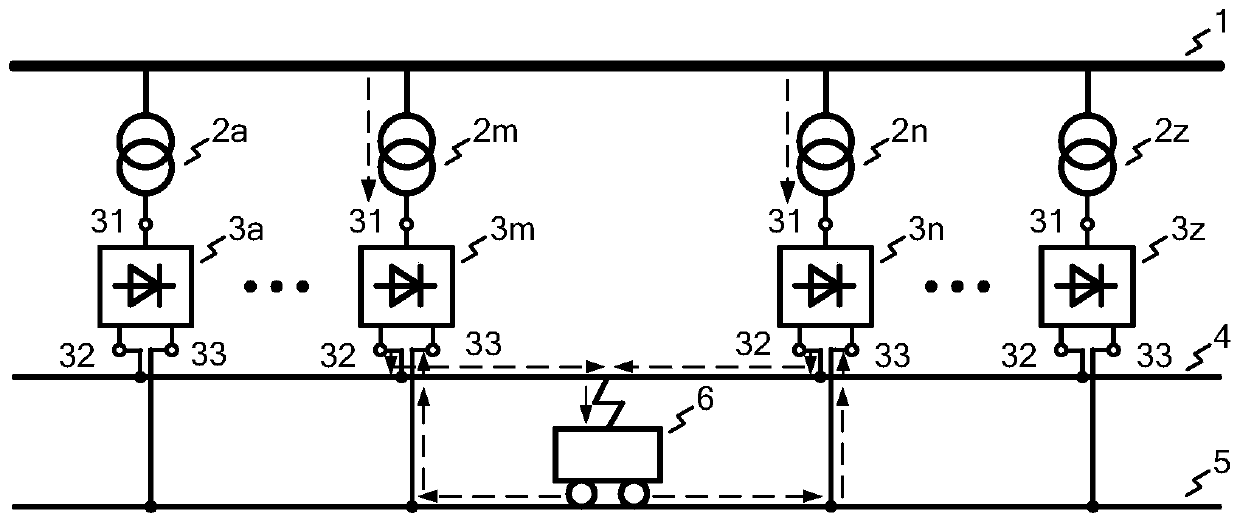
[0059] The existing urban rail transit traction power supply system scheme shown in Figure 1 (a) and (b) includes: a high-voltage AC bus 1, a phase-shifting transformer 2, and a multi-pulse rectifier device 3, which is responsible for distributing electric energy to the train 6 Net (or the third rail) 4 and walking rail 5. The phase-shifting transformer 2 and the multi-pulse rectification device 3 are typical solutions of the traction substation in the existing urban rail transit traction power supply system. Now the train runs between the phase-shifting transformer 2m (or multi-pulse rectification device...


PUM


Abstract

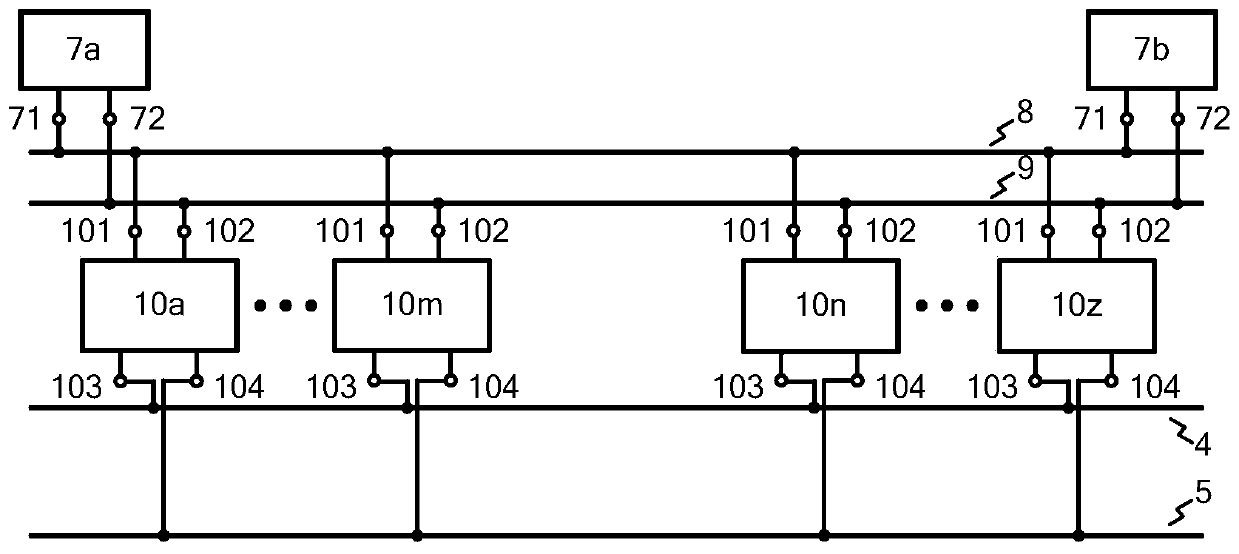
According to a high-voltage direct-current urban rail transit traction power supply system, the input voltage of a main substation is converted into + / -10 kV or direct currents of other voltage classes and distributed to all traction substations, the output positive voltage of a direct traction station is connected to a traction network, and the output zero voltage of the direct traction station is connected to a walking rail. If a negative voltage output by the direct traction station is connected to the return line and the three-end voltage output by the direct current AT in the direct current autotransformer station is respectively connected to the traction network, the running rail and the return line, the direct current AT power supply system is formed. The multifunctional DC transformer in the direct traction station can realize bidirectional energy flow, so that high-voltage DC buses of stations such as a main substation, the direct traction station and a direct coupling stationand all DC capacitors on a traction network can be used as energy buffers during train braking, and the problem of train braking energy utilization is solved from the source. In addition, the systemcan effectively reduce rail potential and stray current.

Description

technical field [0001] The invention relates to the technical field of electrified rail transit and power electronic direct current conversion, in particular to a high-voltage direct current urban rail transit traction power supply system. Background technique [0002] With the development of power electronics technology, rail transit is becoming increasingly mature and developing rapidly. Among them, urban rail transit is widely used in major modern cities in the world due to its advantages of energy saving, land saving, large transportation volume, all-weather, low pollution, and high safety. As of the end of 2018, a total of 185 urban rail transit operating lines have been opened in 35 cities in mainland my country, with a total length of 5,761.4 kilometers. And it is expected that by the end of 2020, the total length of operating lines will exceed 6,000 kilometers. For urban rail transit, DC traction power supply system is mostly used, and relevant domestic standards, ...

Claims


Application Information

Patent Timeline
Patent Type & Authority Applications(China)
IPC IPC(8): H02J5/00H02J3/24H02J1/14H02J3/26B60M3/00
CPCB60M3/00H02J1/14H02J3/24H02J3/26H02J5/00Y02E40/50
Inventor 郑琼林杨晓峰王淼顾靖达游小杰刘建强李虹
Owner BEIJING JIAOTONG UNIV
Learn More