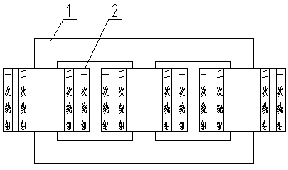
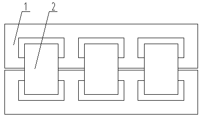
Novel core-type transformer with windings arranged in staggered mode
A transformer and interleaved technology, applied in the field of new transformers, can solve problems such as increasing creepage distance along the surface, doubling ultra-high voltage transformers, and preventing transformer oil from flowing
- Summary
- Abstract
- Description
- Claims
- Application Information
AI Technical Summary
Problems solved by technology
Method used
Image


Examples
example 1
[0114] Example 1. Select S13-400 / 10±2×0.25% / 0.4 transformer as the implementation plan. The reason for the choice is that distribution transformers are extremely sensitive to cost control. In the industry, the cost is generally reduced by sacrificing the sudden short-circuit capability. Therefore, the core and winding cross-sections of distribution transformers are non-circular, so the cost of new transformers is comparable to that of ordinary non-circular cross-sections. Compared with the core transformer, the new type of transformer can reduce the percentage of cost more convincingly under the premise of ensuring the short-circuit capability. Compared with the most common set of drawings in the industry at present, the model of the control group is S13-400 / 10±2×0.25% / 0.4, the iron core and winding section are oval, core transformer, and concentric winding.
[0115] Example 1, S13—400 / 10±2×0.25% / 0.4
[0116] National standard: load loss Pk=4200W
[0117] No-load loss P 0 =...
example 2
[0134] Example 2. HTSSPZ——6300 / 11 electric furnace transformer
[0135] 1. Ferroalloy furnace transformer, capacity 6300KVA, three-phase 11-stage on-load voltage regulation, high voltage 10KV, low voltage 122V-142V, connection group Dd11, cooling method is strong oil circulation water cooling, insulation level LI85AC35 / AC5.
[0136] 2. For the electric furnace transformer of the comparison group, the iron core and winding section are circular, the windings are arranged in a staggered manner, the insulation distance between the high-voltage coil and the low-voltage coil is 25mm, and the distance between the low-voltage coil and the iron yoke is 35mm (pressurized plate).
[0137] 3. A new type of electric furnace transformer with a U-shaped flat-bottom screen. The cross-section of the iron core and windings is oblong. The windings are arranged in a staggered manner.
[0138] The high-voltage coil adopts a U-shaped flat-bottom enclosure, and each high-voltage coil end uses a U-sh...
PUM
| Property | Measurement | Unit |
|---|---|---|
| Load loss | aaaaa | aaaaa |
Abstract
Description
Claims
Application Information
 - R&D
- Intellectual Property
- Life Sciences
- Materials
- Tech Scout
- Unparalleled Data Quality
- Higher Quality Content
- 60% Fewer Hallucinations
Browse by: Latest US Patents, China's latest patents, Technical Efficacy Thesaurus, Application Domain, Technology Topic, Popular Technical Reports.
© 2025 PatSnap. All rights reserved.Legal|Privacy policy|Modern Slavery Act Transparency Statement|Sitemap|About US| Contact US: help@patsnap.com