
A kind of projection objective lens and exposure system

A technology of projection objective lens and lens, applied in the field of projection objective lens optical system, can solve problems such as poor compatibility and incompatibility of exposure system

Active Publication Date: 2021-04-02
SHANGHAI MICRO ELECTRONICS EQUIP (GRP) CO LTD
View PDF2 Cites 0 Cited by
  • Summary
  • Abstract
  • Description
  • Claims
  • Application Information

AI Technical Summary

Problems solved by technology

Among them, the spectral width of the mercury lamp light source and the LED light source are different, the wavelength ranges of the i-line light source and the high three-line light source are different, and the size of the object-side field of view of the stepping exposure and the scanning exposure is different. The exposure system in the prior art usually only The projection objective lens is designed for a certain light source or exposure method, which makes the projection objective lens incompatible with the above three different parameters, resulting in poor compatibility of the exposure system

Method used


Image

  • A kind of projection objective lens and exposure system
  • A kind of projection objective lens and exposure system
  • A kind of projection objective lens and exposure system

Examples


Embodiment Construction

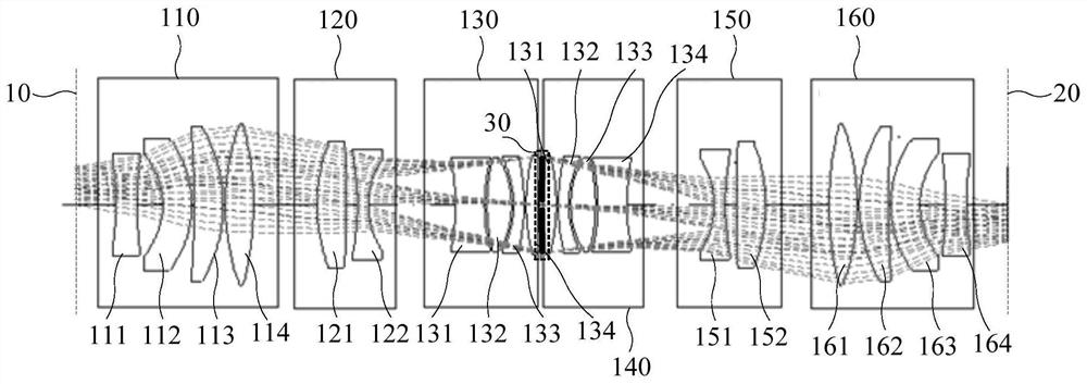
[0030] The present invention will be further described in detail below in conjunction with the accompanying drawings and embodiments. It should be understood that the specific embodiments described here are only used to explain the present invention, but not to limit the present invention. In addition, it should be noted that, for the convenience of description, only parts related to the present invention are shown in the drawings but not all content. Before discussing the exemplary embodiments in more detail, it should be mentioned that some exemplary embodiments are described as processes or methods depicted as flowcharts. Although the flowcharts describe various operations (or steps) as sequential processing, many of the operations may be performed in parallel, concurrently, or simultaneously. In addition, the order of operations can be rearranged. The process may be terminated when its operations are complete, but may also have additional steps not included in the figure...


PUM

PropertyMeasurementUnit
wavelengthaaaaaaaaaa
diameteraaaaaaaaaa

Abstract

The invention discloses a projection objective lens and an exposure system. The projection objective lens comprises a first lens group with positive focal power, a second lens group with negative focal power, a third lens group with positive focal power, an aperture diaphragm, a fourth lens group with positive focal power, a fifth lens group with negative focal power and a sixth lens group with positive focal power which are sequentially arranged from object plane along optical axis, wherein the first lens group and the sixth lens group are symmetrical based on the aperture diaphragm, the second lens group and the fifth lens group are symmetrical based on the aperture diaphragm, the third lens group and the fourth lens group are symmetrical based on the aperture diaphragm, and the following relational expressions are satisfied that f1 / f2 is more than -0.7 and less than -0.3, f2 / f3 is more than -1.1 and less than -0.6, f5 / f4 is more than -1.1 and less than -0.6, f6 / f5 is more than -0.7and less than -0.3, wherein f1, f2, f3, f4, f5, and f6 are the focal lengths of the first lens group, the second lens group, the third lens group, the fourth lens group, the fifth lens group, and thesixth lens group respectively. According to the technical scheme provided by the embodiment of the invention, the compatibility of the projection objective lens is improved, and the modularization level of an exposure system is improved.

Description

technical field [0001] Embodiments of the present invention relate to a projection objective lens optical system, in particular to a projection objective lens and an exposure system. Background technique [0002] Optical lithography is a technology that uses light to project and replicate mask patterns. The device using optical lithography technology is an exposure system. With the help of a projection exposure system, patterns with different mask patterns are imaged on a substrate, such as a silicon wafer. Or LCD panels, used to manufacture integrated circuits, thin-film magnetic heads, liquid crystal display panels, or micro-electromechanical (MEMS) and a series of structures. [0003] The light source of the exposure system includes a mercury lamp light source and an LED light source. The LED light source is further divided into an i-line light source and a high three-line light source. In addition, the basic exposure methods of the exposure system include stepping and sc...

Claims


Application Information

Patent Timeline
Patent Type & Authority Patents(China)
IPC IPC(8): G02B13/00G03F7/20G02B1/00
CPCG02B1/00G02B13/00G03F7/70241
Inventor 侯宝路
Owner SHANGHAI MICRO ELECTRONICS EQUIP (GRP) CO LTD
Learn More