
High-density optical fiber distribution tray

A fiber optic distribution, high-density technology, applied in the field of high-density fiber optic distribution trays, can solve the problem of inconvenient installation and maintenance of distribution optical cables or connecting optical cables, distribution trays cannot be flexibly disassembled from the distribution box, and optical fiber distribution The box space utilization rate is low and other problems, to achieve the effect of compact structure, low duty ratio, and miniaturization

Pending Publication Date: 2020-05-12
惠州市飞博康实业有限公司
View PDF0 Cites 3 Cited by
  • Summary
  • Abstract
  • Description
  • Claims
  • Application Information

AI Technical Summary

Problems solved by technology

Due to the wiring distribution method, convenient use, etc., the volume of the tray cannot be greatly reduced, resulting in low space utilization of the entire optical fiber distribution box, which limits the room for a large increase in the density of the optical fiber distribution box. In practical applications, for To meet the requirement of 144 cores in 1U space, it is necessary to combine multiple optical fiber distribution boxes, resulting in large space occupation and high cost, and there are many different modes of conversion between LC, SC, MTP / MPO in the transmission of optical fibers, which need to be replaced Different distribution trays increase the cost of production and use. In addition, the distribution tray cannot be flexibly disassembled from the distribution box, which is not only inconvenient for the installation and maintenance of distribution optical cables or connecting optical cables

Method used


Image

  • High-density optical fiber distribution tray
  • High-density optical fiber distribution tray
  • High-density optical fiber distribution tray

Examples


Embodiment Construction

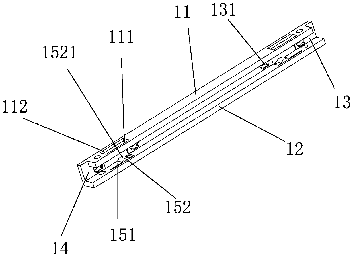
[0031] refer to Figure 1 to Figure 6 , the present invention is realized in this way: the high-density optical fiber distribution tray includes a slide rail 1, a tray body 2 capable of realizing various module conversions between input and output, and the tray body 2 is limited in the slide rail 1 and can be placed on the slide rail 1. Inside the rail 1, the disc body 2 is provided with a wiring area 3, a terminal area 4, a detachable cover body 5 that is clamped with the wiring area 3, and the wiring area 3 is provided with an input installation area 31, an output end The installation area 32 , the fiber storage area 33 arranged between the input end installation area 31 and the output end installation area 32 , the terminal area 4 is set on the side of the output end installation area 32 . The thickness of the disc body 2 is set to be just enough to accommodate an adapter inside, and the thickness of the disc body 2 in the present invention is set to 1.2CM.

[0032] The sl...


PUM


Abstract

The invention discloses a high-density optical fiber distribution tray. The optical fiber distribution tray comprises a tray body, the tray body is provided with a distribution area, a terminal area and a detachable cover body clamped with the distribution area, the distribution area is provided with an input end installation area, an output end installation area and a fiber storage area, the terminal area is arranged on the side face of the output end installation area, and the fiber storage area is provided with a welding clamping base which can be installed in multiple directions and is detachable. The high-density optical fiber distribution tray provided by the invention is small in size, thin in thickness, high in adapter density and reasonable in distribution and wiring, Meanwhile, different welding clamping bases can be dismounted or replaced, so that conversion of multiple modules between input and output is realized. The disc body can be dragged in the sliding rail by pullingthe handle, and the baffle can be dismounted or mounted as required, so that installation and maintenance of a distribution optical cable or a connection optical cable are facilitated. The optical fiber distribution tray is compact in structure, convenient to install and low in duty ratio, and miniaturization and high density of the optical fiber distribution tray are achieved.

Description

technical field [0001] The invention relates to the field of optical fiber adapter accessory technology and optical fiber welding technology in optical communication technology, in particular to a high-density optical fiber distribution tray. Background technique [0002] With the popularization of cloud computing and big data, large-scale data centers have been continuously developed as basic equipment, and at the same time, higher requirements are put forward for the density of optical fiber adapters in optical fiber distribution boxes. Due to the wiring distribution method, convenient use, etc., the volume of the tray cannot be greatly reduced, resulting in low space utilization of the entire optical fiber distribution box, which limits the room for a large increase in the density of the optical fiber distribution box. In practical applications, for To meet the requirement of 144 cores in 1U space, it is necessary to combine multiple optical fiber distribution boxes, resu...

Claims


Application Information

Patent Timeline
IPC IPC(8): G02B6/44G02B6/38
CPCG02B6/3825G02B6/4446G02B6/4452G02B6/3897G02B6/4454G02B6/4455G02B6/4471
Inventor 李尧乐
Owner 惠州市飞博康实业有限公司
Learn More