
Transmission shaft, transmission shaft assembly and transmission shaft welding method

A welding method and transmission shaft technology, applied in welding equipment, couplings, non-electric welding equipment, etc., can solve the problems of high degree of automation, strong professionalism, and large limitations, so as to achieve no loss of welding strength and improve welding seam. Good strength and stability

Pending Publication Date: 2020-05-12
东风汽车底盘系统有限公司
View PDF4 Cites 1 Cited by
  • Summary
  • Abstract
  • Description
  • Claims
  • Application Information

AI Technical Summary

Problems solved by technology

[0004] 1) It is realized by workpiece rotation, friction, and top pressure; 2) The welding heat is large, which reduces the mechanical strength of the base metal around the weld at the joint; 3) The equipment has a high degree of automation and complex technology, strong professionalism, and large limitations. Not suitable for assembly lines and professional production lines for mass production

Method used


Image

  • Transmission shaft, transmission shaft assembly and transmission shaft welding method
  • Transmission shaft, transmission shaft assembly and transmission shaft welding method
  • Transmission shaft, transmission shaft assembly and transmission shaft welding method

Examples


Embodiment Construction

[0038] Many specific details are set forth in the following description to facilitate a full understanding of the embodiments of the present application. However, the embodiment of the present application can be implemented in many other ways different from those described here, and those skilled in the art can make similar promotions without violating the connotation of the embodiment of the present application. Implemented restrictions.

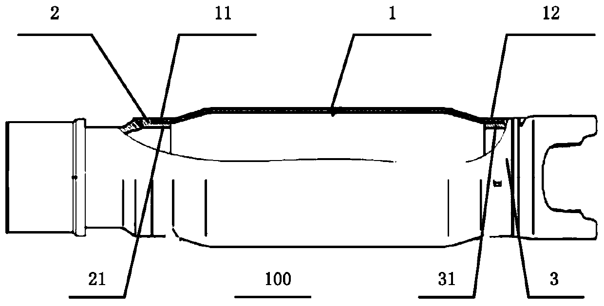
[0039] The first embodiment of the present application provides a drive shaft, figure 1 It is a structural schematic diagram of a drive shaft provided in the first embodiment of the present application;

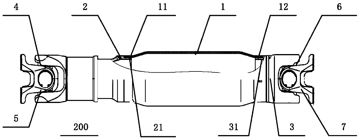
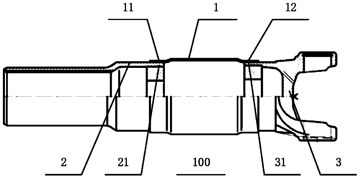
[0040] combine figure 1 As shown, the transmission shaft 100 includes a shaft tube 1 , a spline sleeve 2 and a universal joint yoke 3 . Wherein, the shaft tube 1 has a first end portion 11 and a second end portion 12 , and the first end portion 11 and the second end portion 12 are opposite ends of the shaft tube 1 . The spline sleeve 2...


PUM


Abstract

The invention discloses a transmission shaft. The transmission shaft comprises a shaft tube, a spline sleeve and a universal joint fork, wherein the shaft tube is provided with a first end part and asecond end part; the spline sleeve is inserted into the interior of the first end part of the shaft tube, the inner wall of the first end part of the shaft tube is connected with the outer wall of thespline sleeve through magnetic pulse welding, and the axis of the spline sleeve is coaxial with the axis of the shaft tube; and the universal joint fork is inserted into the interior of the second end part of the shaft tube, the inner wall of the second end part of the shaft tube is connected with the outer wall of the universal joint fork through magnetic pulse welding, and the axis of the universal joint fork is coaxial with the axis of the shaft tube. According to the embodiment, the shaft tube is connected with the spline sleeve and the universal joint fork through magnetic pulse welding,the welding quality stability is good, the welding strength is not lost, namely, the weld joint strength is improved; and the shaft tube is made of an aluminum alloy material, so that the mass of thetransmission shaft is reduced; and the transmission shaft is low in cost and suitable for assembly lines and professional production lines for mass production.

Description

technical field [0001] The present application relates to the technical field of automobile transmission shaft assembly, in particular to a transmission shaft, a transmission shaft assembly, and a transmission shaft welding method. Background technique [0002] In the existing welding process of the shaft tube of the automobile transmission shaft, the universal joint yoke and the sliding spline sleeve, the traditional welding process is basically adopted, for example, flash welding, CO2 gas shielded welding, etc. Its disadvantage is that groove processing must be carried out, and poor welding is prone to occur. The welding deformation at the joint is relatively large, and the bending accuracy is very low. Due to the serious spatter during welding, the assembly surface of the cross is often adhered by molten metal slag, which is difficult to remove, damages assembly accuracy, and has a great impact on product quality. [0003] In recent years, a small number of enterprises ...

Claims


Application Information

Patent Timeline
IPC IPC(8): F16D3/27B23K20/06
CPCF16D3/26B23K20/06
Inventor 张小艳蔡峻豪毛昌吉袁联成祝金贵贾松文
Owner 东风汽车底盘系统有限公司
Learn More