
Distributed flow collection system and edge calculation method

A traffic collection and edge computing technology, applied in computing, computing models, transmission systems, etc., can solve the problems of unstable offline operation of data transmission, high data processing delay and response time, and inability to obtain processing results quickly. The effect of low transmission pressure, improved resource utilization, and reduced performance costs

Active Publication Date: 2020-05-08
DIGITAL CHINA SYST INTEGRATION SERVICE
View PDF9 Cites 17 Cited by
  • Summary
  • Abstract
  • Description
  • Claims
  • Application Information

AI Technical Summary

Problems solved by technology

[0006] (1) The existing technology will occupy a large amount of network bandwidth in the process of traffic data transmission, resulting in network congestion and high delay
[0007] (2) Most of the existing technologies use cloud computing. Massive data uploads will accumulate data in the cloud center, resulting in high data processing delays and response times. Processing results cannot be obtained quickly, resulting in low processing efficiency and high computing and storage costs.
[0008] (3) The existing technology will transfer data to the cloud, and important sensitive information will be transmitted through the network, which may cause privacy leakage during the transmission process
[0009] (4), the existing technology relies heavily on the cloud center, and data transmission cannot run offline stably in areas with limited Internet connections
[0010] Difficulty in solving the above technical problems: At present, the architecture of edge computing still lacks a clear and unified definition. Whether it is in the industrial field or the consumer field, there are many market segments with huge differences in demand, which leads to the diversity of edge computing solutions.

Method used


Image

  • Distributed flow collection system and edge calculation method
  • Distributed flow collection system and edge calculation method
  • Distributed flow collection system and edge calculation method

Examples


Embodiment

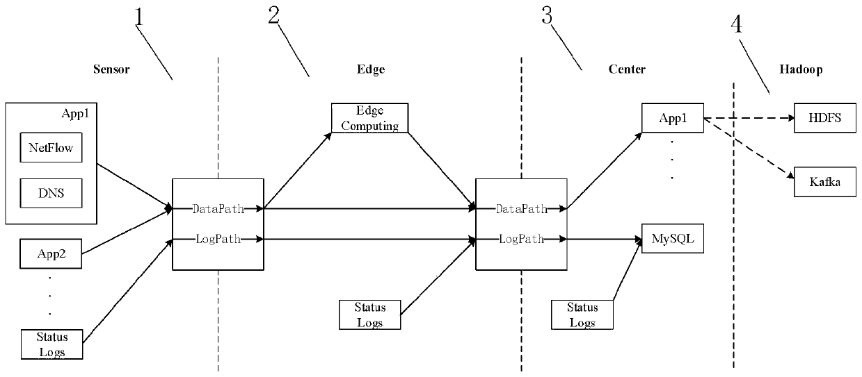
[0076] Configure related flow templates for the data to be calculated on the edge node. The present invention takes DGA malicious domain name detection as example ( Figure 4 ) to build an edge computing instance, and deploy the trained machine learning detection model on the edge node. exist Figure 4 In the present invention, an overview of the entire edge computing model is given, including the device layer, edge layer and cloud center. Due to the complexity of the actual process framework, it is not easy to have an intuitive overview. In order to facilitate the understanding of the data flow, only the components related to the application examples in this section are extracted, and the above-mentioned outline diagram is drawn for display and description.

[0077] At the device layer, the present invention deploys a MiNiFi template for data collection. Firstly, the acquisition device is invoked through the ExecuteProcess processor, and the data packets are continuously c...


PUM


Abstract

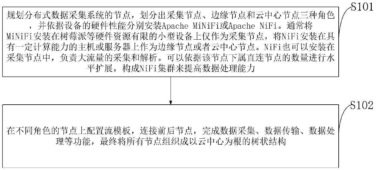
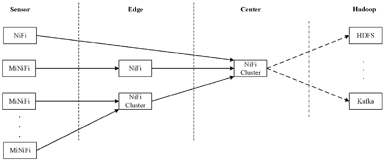
The invention belongs to the technical field of big data cloud computing, and discloses a distributed flow acquisition system and an edge calculation method. The method comprises the following steps:firstly, planning nodes of a distributed data acquisition system, dividing the nodes into acquisition nodes, edge nodes and cloud center nodes, and respectively installing Apache MiNiFi or Apache NiFiaccording to the hardware performance of equipment, secondly, configuring flow templates on the acquisition nodes, the edge nodes and the cloud center nodes, connecting the front and rear nodes to complete functions of data acquisition, data transmission, edge calculation and the like, and organizing all the nodes into a multi-level tree structure taking a cloud center as a root. According to themethod, an edge computing mode in an Internet of Things application scene is used for reference, a machine learning model is deployed to perform distributed parallel processing on data at a place asclose as possible to a data source, and the resource utilization rate and the data processing efficiency are improved.

Description

technical field [0001] The invention belongs to the technical field of big data cloud computing (edge ​​computing), and in particular relates to a distributed flow collection system and an edge computing method. Background technique [0002] Currently, many Internet of Things (IoT) applications, such as smart home, wearable devices, Internet of Vehicles, etc., have been widely used in our daily life. The rapid development of the Internet of Things makes all things interconnected, which provides great convenience for the study, work and life of the present invention. In the IoT scenario, a large number of sensor devices are used to sense the environment, monitor changes and take corresponding actions. Due to the limited computing power and storage capacity of these smart devices, their own performance is not enough to effectively process these sensor data, nor can they perform more complex processing actions. Therefore, a better solution is to use cloud computing. Think of ...

Claims


Application Information

Patent Timeline
IPC IPC(8): H04L29/08G06F9/50G06F16/182G06N20/00
CPCG06F9/5027G06F2209/502G06F16/1824G06N20/00H04L67/10H04L67/1097
Inventor 苏锐丹孙昊
Owner DIGITAL CHINA SYST INTEGRATION SERVICE
Learn More