
Binocular three-dimensional imaging method combining laser dot matrix and polarization vision

A three-dimensional imaging, laser lattice technology, applied in photogrammetry/video surveying, instruments, surveying and navigation, etc., can solve the problems of large amount of calculation, limited measurement accuracy and imaging resolution, affecting imaging results, etc. The effect of simplifying image processing and matching algorithms, enriching surface details, and improving computational accuracy

Inactive Publication Date: 2020-05-08
NANJING UNIV OF SCI & TECH +1
View PDF7 Cites 21 Cited by
  • Summary
  • Abstract
  • Description
  • Claims
  • Application Information

AI Technical Summary

Problems solved by technology

[0004] The binocular vision currently used is mainly based on computer image processing technologies such as grayscale matching and deep learning. All of them are ordinary industrial cameras, but the matching technology based on grayscale is prone to large errors, which seriously affects the imaging results. The imaging accuracy is high when working at a distance. When facing smooth surfaces, low-texture, and high-reflectivity surfaces, large-scale mismatches are more likely to occur, resulting in data holes. The 3D image restoration algorithm is complex, and the amount of calculation is large, so it is not easy to achieve high-speed imaging.
[0005] Some binocular vision combines structured light, wired structured light, point structured light and pulse laser ranging, but this technology has relatively high requirements for real-time processing of optical signals, measurement accuracy and imaging resolution are limited, and it is not suitable for use Suitable for processing smooth surface, low texture, high reflectivity object surface

Method used


Image

  • Binocular three-dimensional imaging method combining laser dot matrix and polarization vision
  • Binocular three-dimensional imaging method combining laser dot matrix and polarization vision
  • Binocular three-dimensional imaging method combining laser dot matrix and polarization vision

Examples


Embodiment

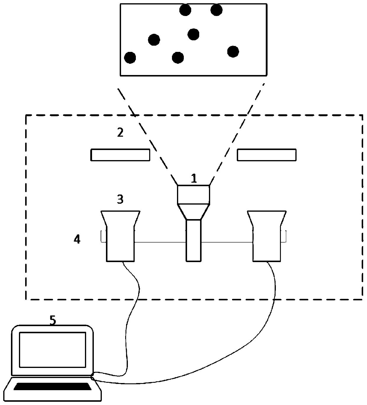
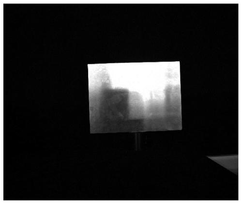
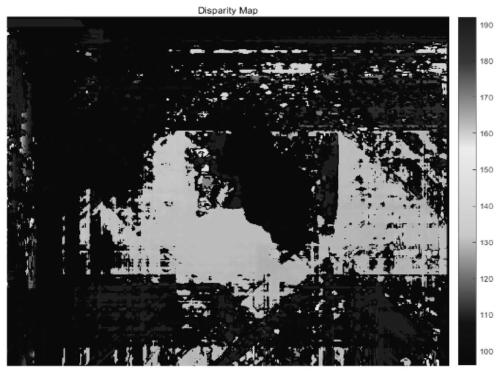
[0042] Such as figure 1 As shown, a three-dimensional imaging method based on binocular vision and polarization imaging combined with laser dot matrix is ​​realized based on an imaging system. The system includes: random dot matrix laser module 1, lens group module 2, binocular polarization camera 3, fixed PTZ 4, computer 5. The imaging method includes the following steps: firstly project the laser dot matrix formed by the laser dot matrix system onto the target object, using the laser as the light source can ensure the singleness and reduce the interference of ambient light, and the density of the dot matrix formed by the dot matrix system determines the follow-up The fineness of the point cloud; then use the polarization camera to obtain the target image pair, and get more than four pairs of polarization images at different angles. The smooth surface of the object often has a flare phenomenon when imaging, which is due to the overshoot of the camera pixels caused by specular...


PUM


Abstract

The invention discloses a binocular three-dimensional imaging method combining a laser dot matrix and polarization vision. The binocular three-dimensional imaging method comprises the steps of: enabling laser dot matrix projection formed by means of a random dot matrix laser module to act on a target object; filtering to reduce interference of ambient light and suppress part of flare by means of alens group module; and finally, using a binocular polarization camera for capturing an effective target image pair, carrying out point matching on the two images, and then calculating parallax and three-dimensional coordinates to form a target surface three-dimensional point cloud image. According to the binocular three-dimensional imaging method, the polarization camera is used for replacing a common visible light camera, background light is suppressed by means of the filter, surface flare is suppressed by using polarization imaging, and the number of saturation points in all pixel points covered by light spots in an image is reduced, so that the calculation precision of the centers of the light spots is improved, the defects of a traditional binocular vision system are overcome, and thebinocular three-dimensional imaging method can be applied to a metal-like target with a smooth surface, low texture and high reflection.

Description

technical field [0001] The invention relates to binocular three-dimensional imaging technology, in particular to a binocular three-dimensional imaging method combining laser dot matrix and polarization vision. Background technique [0002] Binocular stereo vision distance measurement technology is a non-contact distance measurement technology, which is an application of binocular stereo vision in computer vision. It mainly uses a computer to simulate binoculars, and matches two or more images obtained by the imaging device. These images can be taken by the same camera at different angles or positions in time-sharing, or can be taken by different cameras at the same time; and then Calculate the parallax of the target point, and calculate the relative coordinates and world coordinates of the target point according to the principle of triangulation, so as to restore the depth information, obtain the surface topography of the target, and realize three-dimensional reconstruction....

Claims


Application Information

Patent Timeline
IPC IPC(8): G01C11/00
CPCG01C11/00
Inventor 陆健刘晓刚刘礼城林新迪张宏超
Owner NANJING UNIV OF SCI & TECH
Learn More