Calibration tool for a magnetic suction stamping tool holder chip detection device

A detection device, stamping technology, applied in positioning devices, manufacturing tools, clamping, etc., can solve the problem that the chip detection device does not have calibration tools, etc.

Active Publication Date: 2020-07-07
上海交通大学烟台信息技术研究院 +1
View PDF8 Cites 0 Cited by
  • Summary
  • Abstract
  • Description
  • Claims
  • Application Information

AI Technical Summary

Problems solved by technology

[0004] Aiming at the problem that there is no special calibration tool for the chip detection device in the prior art, a calibration tool for the chip detection device of a magnetic suction punching tool holder is provided

Method used


Image

  • Calibration tool for a magnetic suction stamping tool holder chip detection device
  • Calibration tool for a magnetic suction stamping tool holder chip detection device

Examples


Embodiment 1

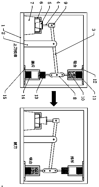
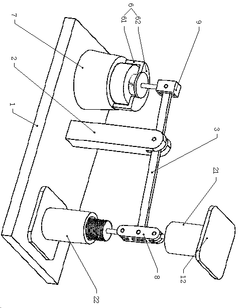
[0023] Embodiment 1, a calibration tool for a magnetic suction stamping tool holder chip detection device, including a calibration bench 1, a support arm 2, a lever 3, a fixed frame 6, a mounting seat 7, a power arm hinge connection block 8, and a resistance arm hinge Connecting block 9, top moving electromagnet 10, top fixed electromagnet 11 and top fixed seat 12.

[0024] The support arm 2 is set on the calibration bench 1, its upper end is hinged with the middle part of the lever 3, the front end of the lever 3 is hinged with the resistance arm hinge block 9, and its rear end is hinged with the power arm hinge block 8.

[0025] The top fixing seat 12 is installed on the top of the calibration stand 1, which extends downwards to form a top sleeve 21, the top fixed electromagnet 11 is fixedly installed on the top of the top sleeve 21, and the top moving electromagnet 10 can be arranged on the top sleeve so that it can slide up and down. In the cylinder 21, the lower end of th...

Embodiment 2

[0029] Embodiment 2, on the basis of Embodiment 1, further includes a bottom moving electromagnet 13 , a bottom fixing electromagnet 14 and a bottom fixing seat 15 . The bottom fixing seat 15 is installed on the bottom of the calibration stand 1, and it extends upwards to form a bottom sleeve 22. The bottom fixed electromagnet 14 is fixedly installed on the bottom of the bottom sleeve 22, and the bottom moving electromagnet 13 is arranged on the bottom sleeve so that it can slide up and down. 22, the upper end of the bottom motion electromagnet 13 is hinged with the power arm hinge connection block 8 through the connecting rod.

[0030] In this embodiment, through the upper and lower pairs of electromagnets, there are two functions. One is that the two pairs of electromagnets form a combined force to obtain a larger output of the upper knife force; the other is that the lower pair of electromagnets are in the process of drawing the knife. It can provide magnetic attraction to ...


PUM


Abstract

The invention discloses a calibration tool for a magnetic-suction stamping tool handle chip detection device, which includes a calibration stand, a support arm, a lever, a simulated tool handle, a fixing frame, a mounting seat, a hinge connection block of a power arm, and a hinge connection block of a resistance arm , the top moving electromagnet, the bottom moving electromagnet, the bottom fixed electromagnet and the bottom fixed seat; the support arm is arranged on the calibration bench, its upper end is hinged with the middle part of the lever, and the front end of the lever is hinged with the resistance arm hinge connection block , the rear end of which is hinged with the hinge connection block of the power arm; the simulated knife handle is connected with the hinge connection block of the resistance arm through a connecting rod, the mounting seat is set on the calibration bench, and the fixing frame is set on the mounting seat for fixing the pending calibration and debugging The shank chip detection device. Beneficial effects of the present invention: the two power output units of the calibration tool are suction-pull matched, and the power output is strong, and the calibration work of the chip detection device can be completed without using the electric spindle broaching mechanism of the machining center.

Description

technical field [0001] The invention belongs to the technical field of machine tool components, and in particular relates to a calibration tool. Background technique [0002] CNC machine tools are the main machine tools of the equipment manufacturing industry, and their technical level represents the development level of a country's manufacturing industry. The machining center is the first important member of the CNC machine tool. Due to the concentration of processes and automatic tool change in the machining center, the time for clamping, measuring and machine tool adjustment of the workpiece is reduced, so that the cutting time of the machine tool reaches about 80% of the machine tool start-up time (only 15-20% for ordinary machine tools); at the same time It also reduces the workpiece turnover, handling and storage time between processes, shortens the production cycle, and has obvious economic effects. With the continuous improvement of the requirements for high-precis...

Claims


Application Information

Patent Timeline
Patent Type & Authority Patents(China)
IPC IPC(8): B23Q3/155B23Q17/22
CPCB23Q3/15506B23Q17/22
Inventor 柴永生李林王昌辉刘宇航刘咪闵晓晨卫尚涛张茂源陈义保
Owner 上海交通大学烟台信息技术研究院
Why Eureka
Try Eureka