A winding type drawing top heading pipe bending machine

A kind of upsetting pipe bending machine, winding technology, applied in the field of winding type drawing top upsetting pipe bending machine, to achieve the effect of stable transmission, improved efficiency and flexible action

Active Publication Date: 2017-07-04
ANHUI DEXI DHI TECH
View PDF3 Cites 0 Cited by
  • Summary
  • Abstract
  • Description
  • Claims
  • Application Information

AI Technical Summary

Problems solved by technology

[0005] Aiming at the problem that the clamping mold of the existing top heading pipe bender interferes with the pipe fittings when it is reset, the present invention provides a winding type drawing top heading pipe bending machine, which adopts a climbing type clamping device, which can realize the independent reset of the main mold, thereby The above-mentioned problems are effectively solved, and at the same time, it has the effects of simple structure, flexible action, and can reduce the difficulty of processing pipe fittings.

Method used


Image

  • A winding type drawing top heading pipe bending machine
  • A winding type drawing top heading pipe bending machine
  • A winding type drawing top heading pipe bending machine

Examples


Embodiment 1

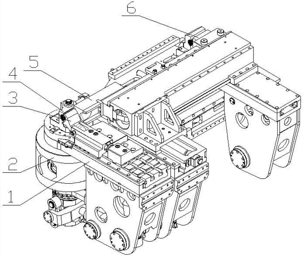
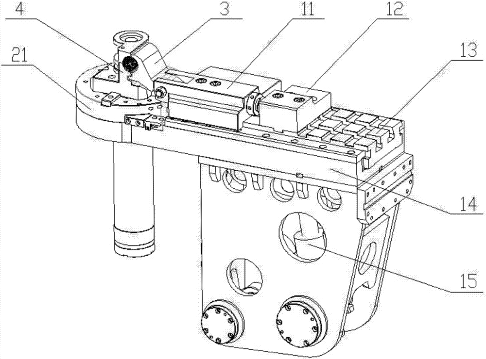
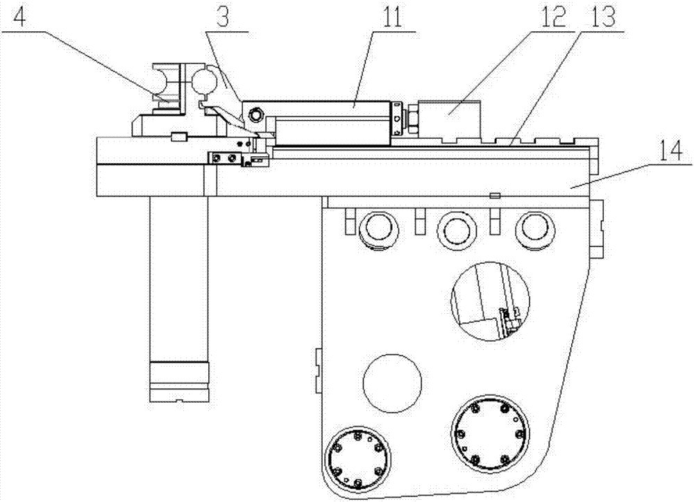
[0047] Such as figure 1 As shown, a winding type drawing top heading pipe bender includes a clamping device 1, a main mold reset device 2, a clamping mold 3, a main mold 4, a pressing rail mold 5, and a top heading mechanism 6, such as Figure 13 As shown, the master mold resetting device 2 includes a master mold holder 21, a master mold support 22 and a master mold holder gear 24; as figure 2 , image 3 and Figure 4 As shown, the clamping device 1 includes a clamping mold base 11, a slider 13, a slider base 14 and a slider drive 15;

[0048] The main mold holder 21 is rotatably arranged on the main mold support 22, specifically as Figure 14 As shown, the main mold support 22 is a hollow structure, the upper end of the main mold 21 is connected with the upper end surface bearing of the main mold support 22, and the lower end passes through the main mold support 22 and is fixedly connected with the main mold holder gear 24; Main mold support 22 is connected by bearing, a...

Embodiment 2

[0060] A winding type drawing and upsetting pipe bending machine, which is basically the same as that of Embodiment 1, except that a track is provided on the upper surface of the slider 13 close to the main mold 4, and a T-shaped groove is provided on the other side; Figure 5 or Figure 11 As shown, the mold clamping seat 11 is arranged on the track, and is fixed by a set bolt 116, and the clamping mold positioning seat 12 is arranged on the T-shaped slot, and is fixed by a set bolt 121; Figure 5 As shown, the clamping mold base 11 is provided with a clamping mold fixing groove 111 at one end close to the main mold 4, and the clamping mold 3 is rotatably arranged in the clamping mold fixing groove 111 through a pin shaft, and the other end of the clamping mold base 11 is provided with a clamping mold fine-tuning Rod 112, clamping mold fine-tuning lever 112 one end is threadedly connected with the end face of clamping mold base 11, and the other end contacts with clamping mol...


PUM


Abstract

The invention discloses a winding-type drawing upsetting pipe bending machine, belongs to the field of pipe bending machinery, and aims to solve the problem that a clamping mold of the conventional upsetting pipe bending machine interferes with a pipe fitting during resetting, so that production is impacted and restricted. The winding-type drawing upsetting pipe bending machine comprises a clamping device, a clamping mold and a main mold, wherein the clamping device comprises a clamping mold seat, a sliding block, a sliding block seat and a sliding block drive; a sliding rail is arranged on the upper surface of the sliding block seat; the sliding block is arranged on the sliding rail; the sliding block drive is connected with the sliding block; the clamping mold seat is fixedly arranged on the sliding block; the clamping mold is rotationally arranged at the end, near the main mold, of the clamping mold seat through a pin shaft; a slope block is arranged on the side, corresponding to the clamping mold, at the lower end of the main mold. The winding-type drawing upsetting pipe bending machine has the advantages that a mechanism can be simplified; impact of interference can be avoided; the action is flexible; the difficulty of pipe fitting processing is lowered.

Description

technical field [0001] The invention belongs to the field of pipe bending machines, and in particular relates to a winding type drawing top heading pipe bending machine. Background technique [0002] Pipe fittings with bending angles are widely used in the field of pipeline transportation, especially for pipeline transportation technology that requires high precision. The uniformity of wall thickness of pipe fittings, uniformity of bending angles, roundness of inner and outer walls of bends, etc. determine the quality of pipe fittings. The bending of pipe fittings is realized by a pipe bender, which is a machine that bends pipe fittings. The pipe bending machine generally includes main mold, clamping mold, pressing rail mold, top heading mechanism, top heading clamping mold, anti-wrinkle mold and other components. For example, the Chinese patent application number 200710040527.7, the patent application document published on October 10, 2007, discloses a processing method an...

Claims


Application Information

Patent Timeline
Patent Type & Authority Patents(China)
IPC IPC(8): B21D7/024B21D43/00
CPCB21D7/024B21D43/003
Inventor 吴善普吴善照
Owner ANHUI DEXI DHI TECH
Why Eureka
Try Eureka