Air inlet device of combustible waste heat recovery system

An air inlet device and heat recovery technology, applied in the combustion method, combustion type, lighting and heating equipment, etc., can solve the problems of shortening the service life, energy consumption, the temperature of the combustion furnace cannot reach the maximum value, etc., and reduce the heat of the flue gas. The effect of reducing the loss, speeding up the conveying, and better air intake effect

Inactive Publication Date: 2020-05-05
北京百年初心科技有限公司
View PDF0 Cites 2 Cited by
  • Summary
  • Abstract
  • Description
  • Claims
  • Application Information

AI Technical Summary

Problems solved by technology

The air intake device in the existing heat recovery system usually adopts the method of installing a fan in the exhaust pipe to speed up the flow rate of the flue gas, thereby preventing the heat loss of the flue gas in the pipe, and because the temperature of the high-temperature flue gas can generally reach two 100 degrees Celsius, the fan blades will be deformed in such a high temperature environment, and the service life of the fan motor will be greatly shortened if the fan motor runs under high load conditions, and the existing smoke exhaust pipe is always in communication with the combustion furnace, so the combustion furnace is in the initial combustion During the process, part of the heat will flow directly into the heat recovery device from the exhaust pipe, so that the temperature in the combustion furnace cannot reach the maximum value. The recovery device will also consume a certain amount of energy during operation, which will also increase the cost. Therefore, an air intake device is needed to ensure the efficient operation of the heat recovery system

Method used


Image

  • Air inlet device of combustible waste heat recovery system
  • Air inlet device of combustible waste heat recovery system
  • Air inlet device of combustible waste heat recovery system

Examples


Embodiment Construction

[0020] In order to make the technical solution of the present invention clearer, the present invention will be further described below in conjunction with the accompanying drawings. Any solution obtained by equivalent replacement and conventional reasoning of the technical features of the technical solution of the present invention falls within the protection scope of the present invention. The fixed connection mentioned in the present invention and the fixed arrangement are common connection methods in the mechanical field, and welding, bolt and nut connection and screw connection are all available.

[0021] In describing the present invention, it is to be understood that the terms "upper", "lower", "front", "rear", "left", "right", "vertical", "horizontal", "top" , "bottom", "inner", "outer" and other indicated orientations or positional relationships are based on the orientations or positional relationships shown in the drawings, and are only for the convenience of describin...


PUM


Abstract

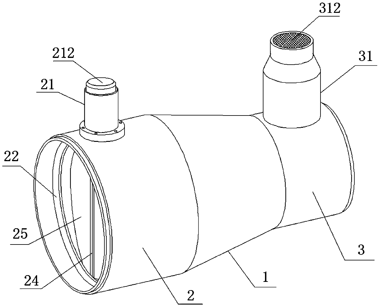
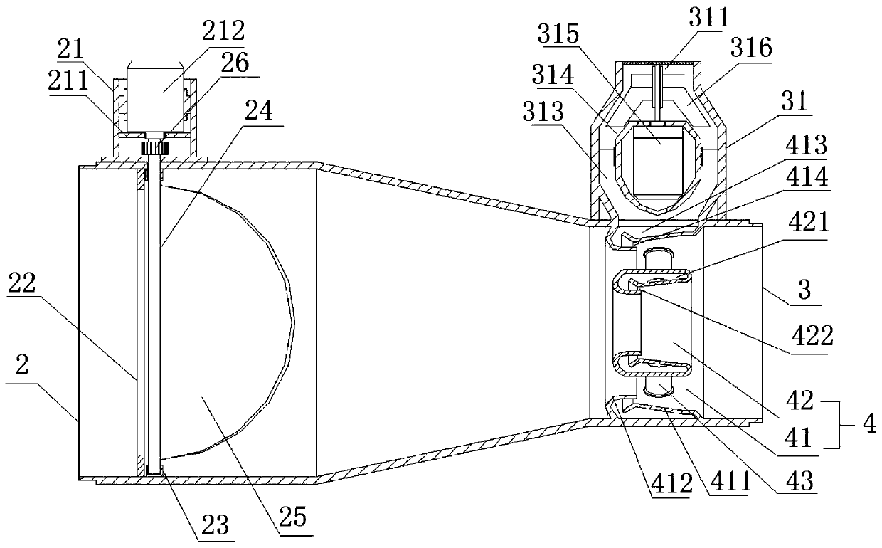
The invention relates to an air inlet device of a combustible waste heat recovery system. The air inlet device comprises an air hose body, an air inlet pipe and an air outlet pipe are correspondinglyarranged at two ends of the air hose body, and an air injecting assembly is arranged in an inner cavity of the air outlet pipe. The air injecting assembly comprises an outer nozzle and an inner nozzle, the outer nozzle comprises an annular flow-guiding cover and an annular drainage cover, a first airflow channel is formed between the drainage cover and the inner wall of the air outlet pipe, the flow-guiding cover is located at the other end of the drainage cover, and one end of the flow-guiding cover is close to the outer wall of the drainage cover and a first exhaust hole is formed; an innercavity of the inner nozzle is provided with a second airflow channel, a second exhaust hole is formed in an inner ring of the inner nozzle, and an air delivery pipe is connected between the inner nozzle and the outer nozzle; and a draught fan seat is arranged on the outer wall of the air outlet pipe, an air inlet cavity is formed in the draught fan seat, the lower end of the air inlet cavity communicates with the first airflow channel, a draught fan cover is arranged in the air inlet cavity, a draught fan is arranged in the draught fan cover, and an impeller used for generating airflow is arranged on an output shaft of the draught fan. Conveying of flue gas is accelerated, and the heat loss of the flue gas is reduced.

Description

technical field [0001] The invention belongs to the technical field of heat recovery devices, and in particular relates to an air inlet device of a combustible waste heat recovery system. Background technique [0002] At present, many combustible wastes are generated in the process of industrial processing and production. These combustible wastes are generally disposed of through incineration, and these wastes will generate a lot of heat when they are burned, and the heat will be in vain with the exhaust gas. Wasted, so a heat recovery system is needed to recover heat from these high-temperature flue gases. The air intake device in the existing heat recovery system usually adopts the method of installing a fan in the exhaust pipe to speed up the flow rate of the flue gas, thereby preventing the heat loss of the flue gas in the pipe, and because the temperature of the high-temperature flue gas can generally reach two 100 degrees Celsius, the fan blades will be deformed in su...

Claims


Application Information

Patent Timeline
Patent Type & Authority Applications(China)
IPC IPC(8): F23G5/46F23L15/04
CPCF23G5/46F23G2206/20F23L15/04Y02E20/34
Inventor 崔建中
Owner 北京百年初心科技有限公司
Why Eureka
Try Eureka