A sewage tail water heat recovery device

A heat recovery device and tail water technology, applied in the direction of indirect heat exchangers, heat exchanger types, heat exchange equipment, etc., can solve the problems of difficult heat exchange unit power, reduced heat collection efficiency, adaptation, etc., to reduce maintenance frequency , avoid wasting energy, reduce the effect of being

Active Publication Date: 2021-06-01
淮安市建筑设计研究院有限公司
View PDF0 Cites 0 Cited by
  • Summary
  • Abstract
  • Description
  • Claims
  • Application Information

AI Technical Summary

Problems solved by technology

[0002] In production and life, various kinds of sewage or tail water containing high heat are often discharged to the outside world. Effectively recovering the heat in the sewage tail water to form high-temperature production and domestic water can greatly reduce carbon emissions. Based on this, the current There are technologies to install heat recovery devices for sewage tail water in some buildings, but since the flow and temperature of sewage tail water are difficult to predict in real time, it is difficult for the power of subsequent heat exchange units to adapt to the sewage tail water, and excessive sewage tail water flow After passing through the heat exchange unit, a large amount of heat-resistant dirt layer will quickly adhere to the surface of the heat exchange unit, which will greatly reduce the heat collection efficiency. In the end, the power heat consumed by the entire device is much greater than the recovered heat, and the energy-saving measures are reduced to decorations.

Method used


Image

  • A sewage tail water heat recovery device
  • A sewage tail water heat recovery device

Examples


Embodiment Construction

[0013] The present invention will be further described below in conjunction with accompanying drawing of description and embodiment:

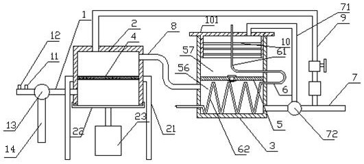
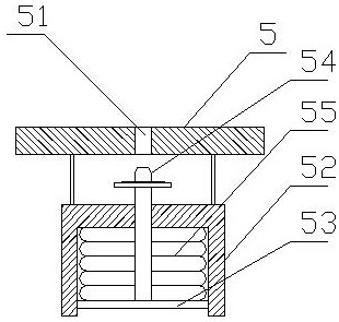
[0014] Such as figure 1 with figure 2 The shown sewage tail water heat recovery device includes a water supply pipe 1, a filter box 2 and a heat exchange box 3, the water supply pipe is connected to the filter box, and a filter screen 4 is arranged in the filter box; a partition is arranged in the middle of the heat exchange box 5. The partition divides the heat exchange box into a high-heat area 56 and a low-heat area 57. A permeable hole 51 is provided in the middle of the partition. A guide sleeve 52 opposite to the permeable hole is provided on the side of the high-heat area of ​​the permeable hole. Inside the guide sleeve is a Sliding plate 53, the middle part of the sliding plate is connected with a sealing rod 54 opposite to the permeable hole, and the sliding plate is connected with an elastic airbag 55, and when the elastic airbag is...


PUM


Abstract

The invention relates to a sewage tail water heat recovery device. A high heat area and a low heat area are set in a heat exchange box. When the heat of the sewage tail water is high, the elastic airbag expands so that the sewage tail water in the high heat area flows to the low heat area, increasing The heat exchange contact time between the sewage tail water and the heat exchange tube increases heat recovery; when the heat of the sewage tail water is low, only the sewage tail water only flows through the high heat area, that is, it only contacts the heat exchange tube in the high heat area, thus effectively Avoid unnecessary contact between the preheating section of the heat exchange tube and the sewage tail water, reduce the degree of pollution of the outer wall of the heat exchange tube, and the conduction or cut-off between the high heat area and the low heat area is realized by the stretchable elastic air bag , no need for electronic circuit components to work inside the harsh heat exchange box, it is not easy to damage and fail, and the maintenance frequency is reduced; in addition, by connecting the drain pipe next to the water supply pipe, when the temperature or flow of the sewage tail water is too low, the sewage tail water can be directly discharged Discharge to the external sewage treatment tank to avoid waste of energy in inefficient heat exchange.

Description

technical field [0001] The invention relates to the technical field of energy saving, in particular to a waste water tail water heat recovery device. Background technique [0002] In production and life, various kinds of sewage or tail water containing high heat are often discharged to the outside world. Effectively recovering the heat in the sewage tail water to form high-temperature production and domestic water can greatly reduce carbon emissions. Based on this, the current There are technologies to install heat recovery devices for sewage tail water in some buildings, but since the flow and temperature of sewage tail water are difficult to predict in real time, it is difficult for the power of subsequent heat exchange units to adapt to the sewage tail water, and excessive sewage tail water flow After passing through the heat exchange unit, a large amount of heat-resisting dirt layer will quickly adhere to the surface of the heat exchange unit, which will greatly reduce t...

Claims


Application Information

Patent Timeline
Patent Type & Authority Patents(China)
IPC IPC(8): F28D7/00F28F19/01F28F9/00F28F27/02B01D29/03B01D35/02
CPCB01D29/03B01D35/02F28D7/00F28F9/005F28F19/01F28F27/02
Inventor 马超罗艳赵焱
Owner 淮安市建筑设计研究院有限公司
Why Eureka
Try Eureka