An integrated catalytic conversion system and method for reducing tail gas ammonia emissions
A technology of tail gas and catalyst, applied in the field of integrated catalytic conversion system, can solve problems such as ammonia escape and achieve high efficiency
- Summary
- Abstract
- Description
- Claims
- Application Information
AI Technical Summary
Problems solved by technology
Method used
Image


Examples
Embodiment 1
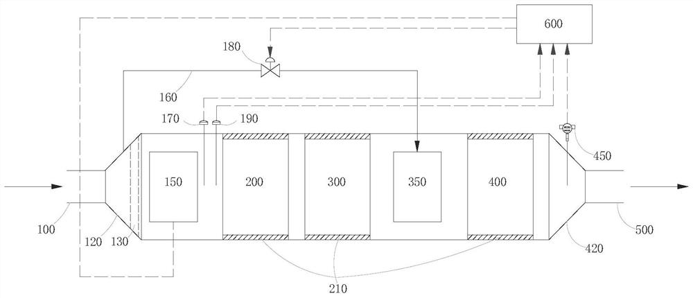
[0089] Introduce 2000ppmv ammonia-containing tail gas from the tail gas inlet 100 into the flow interface expansion section 120, wherein the 100% (V / V) ammonia-containing tail gas enters the flow interface under the action of the air distribution device 130 The airflow inside the expansion section 120 is evenly distributed when the flow interface expands, and then enters the thermal management device 150 (external burner) to adjust the temperature. After the temperature is adjusted, it enters the ammonia removal catalyst module 200 to perform the ammonia removal reaction. The controlled temperature is 250℃, space speed ratio is 5000h -1 , gas velocity 2m·s -1 , the catalyst is a Co-Mn composite oxide catalyst, so that most of the NH in the ammonia-containing tail gas stream to be treated 3 (ammonia) into N 2 (nitrogen) and H 2 O (water). After the ammonia removal reaction is completed, the tail gas flow enters the ammonia oxidation catalyst module 300 to carry out the ammo...
Embodiment 2
[0093] Introduce 5000ppmv ammonia-containing tail gas from the tail gas inlet 100 into the flow interface expansion section 120, wherein 85% (V / V) of the ammonia-containing tail gas enters the flow interface under the action of the air distribution device 130 The airflow inside the expansion section 120 is evenly distributed when the flow interface expands, and then enters the thermal management device 150 (external burner) to adjust the temperature. After the temperature is adjusted, it enters the ammonia removal catalyst module 200 to perform the ammonia removal reaction. The controlled temperature is 400℃, space speed ratio is 10000h -1 , gas velocity 8m·s -1 , the catalyst is a Cu-Mn composite oxide catalyst, so that most of the NH in the ammonia-containing tail gas stream to be treated 3 (ammonia) into N 2 (nitrogen) and H 2 O (water). After the ammonia removal reaction is completed, the tail gas flow enters the ammonia oxidation catalyst module 300 to carry out the a...
Embodiment 3
[0097] 10000ppmv ammonia-containing tail gas to be treated is introduced from the tail gas inlet 100 into the flow interface expansion section 120, wherein 70% (V / V) ammonia-containing tail gas to be treated enters the flow interface under the action of the air distribution device 130 The airflow inside the expansion section 120 is evenly distributed when the flow interface expands, and then enters the thermal management device 150 (external burner) to adjust the temperature. After the temperature is adjusted, it enters the ammonia removal catalyst module 200 to perform the ammonia removal reaction. The controlled temperature is 500℃, space speed ratio is 20000h -1 , gas velocity 15m·s -1 , the catalyst is a Co-Cu-Mn composite oxide catalyst, so that most of the NH in the ammonia-containing tail gas stream to be treated 3 (ammonia) into N 2 (nitrogen) and H 2 O (water). After the ammonia removal reaction is completed, the tail gas flow enters the ammonia oxidation catalyst...
PUM
 Abstract
Description
Claims
Application Information
 - R&D
- Intellectual Property
- Life Sciences
- Materials
- Tech Scout
- Unparalleled Data Quality
- Higher Quality Content
- 60% Fewer Hallucinations
Browse by: Latest US Patents, China's latest patents, Technical Efficacy Thesaurus, Application Domain, Technology Topic, Popular Technical Reports.
© 2025 PatSnap. All rights reserved.Legal|Privacy policy|Modern Slavery Act Transparency Statement|Sitemap|About US| Contact US: help@patsnap.com