
Method for preparing thermal barrier coating CMAS-alienated surface by utilizing picosecond laser

A technology of thermal barrier coating and picosecond laser, which is applied in coating, metal material coating process, etc., can solve the problems of accelerated phase change failure of coating materials, lack of resistance to CMAS, and decreased service life of thermal barrier coatings. Achieve the effect of reducing surface contact area, improving CMAS corrosion resistance, and high practical application value

Inactive Publication Date: 2020-04-21
JIANGSU UNIV
View PDF3 Cites 7 Cited by
  • Summary
  • Abstract
  • Description
  • Claims
  • Application Information

AI Technical Summary

Problems solved by technology

The melting point of CMAS is usually 1100-1300°C. In a high-temperature service environment, the molten CMAS will cause serious damage to the turbine blades. The main performance is to accelerate the phase change failure of the coating material and promote the peeling of the coating. Layer lifetime drops by more than 70%
Since the CMAS corrosion problem was usually ignored in the development of turbine engines in the past, the traditional methods (thermal spraying method, prepared thermal barrier coating preparation method did not have the ability to resist CMAS, and it was not until these years that people began to realize the problem. Severity. Scholars at home and abroad have conducted many studies on the corrosion of CMAS. The new thermal barrier coating material can react with CMAS to form a substance with a high melting point, and inhibit the reaction between the coating and CMAS.

Method used


Image

  • Method for preparing thermal barrier coating CMAS-alienated surface by utilizing picosecond laser
  • Method for preparing thermal barrier coating CMAS-alienated surface by utilizing picosecond laser
  • Method for preparing thermal barrier coating CMAS-alienated surface by utilizing picosecond laser

Examples


Embodiment Construction

[0019] Specific embodiments will be described in detail below in conjunction with specific drawings of the present invention.

[0020] A method of preparing a thermal barrier coating away from the CMAS surface using a picosecond laser in this embodiment, the preparation method includes the following steps:

[0021] The first step: mix 8wt.%Y 2 o 3 , 92wt.% ZrO 2 The powder (99.5%, particle size about 0.5 μm) was placed in a zirconia ball milling tank, and alcohol was used as the ball milling medium, and ball milled on a planetary ball mill for 24 hours, and then the powder was taken out and dried in a drying oven at 80°C for 12 hours. The powder was pressed into discs under a pressure of 20 MPa by dry pressing method, and then the discs were placed in a high-temperature sintering furnace at 1450°C for 4 hours, and sintered to obtain 8YSZ thermal barrier coating.

[0022] Step 2: First, rough grind the 8YSZ thermal barrier coating with silicon carbide sandpaper, and then use...


PUM

PropertyMeasurementUnit
particle sizeaaaaaaaaaa

Abstract

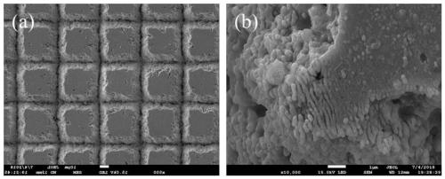
The invention relates to the technical field of thermal barrier coating protection, in particular to a method for preparing a thermal barrier coating CMAS-alienated surface with a micro-nano structureby utilizing picosecond laser. According to the method, the micro-nano structure is prepared on the surface of a thermal barrier coating through the picosecond laser, the material of the thermal barrier coating does not need to be changed, the three-layer structure of a traditional thermal barrier coating does not need to be changed, and therefore the thermophysical performance and the using performance of the coating cannot be affected. On the basis of maintaining the original performance of the thermal barrier coating, the surface micro-nano structure is beneficial to reducing the surface contact area between CMAS and the coating, reducing the adhesion force, and remarkably increasing the contact angle of the molten CMAS on the surface of the thermal barrier coating, so that the CMAS rolls away from the coating, the coating is physically isolated from the CMAS, and the CMAS corrosion resistance of the thermal barrier coating is greatly improved.

Description

technical field [0001] The invention relates to the technical field of thermal barrier coating protection, in particular to a method for preparing a thermal barrier coating with a micro-nano structure by using a picosecond laser to separate from the CMAS surface. Background technique [0002] In recent years, my country's aerospace technology has developed rapidly, and increasing the turbine inlet temperature is an important means to increase engine thrust. For every 10% increase in the thrust-to-weight ratio of the engine, the temperature at the turbine inlet needs to be increased by 100°C. The turbine blades of aero-engines are usually made of superalloys. However, the service temperature of superalloys is relatively limited. Traditional nickel-based superalloys can only withstand high temperatures of more than 1,000 degrees Celsius. Therefore, under such high-temperature and high-stress complex environmental conditions, it is difficult to further improve the high-tempera...

Claims


Application Information

Patent Timeline
Patent Type & Authority Applications(China)
IPC IPC(8): C23C24/10
CPCC23C24/10
Inventor 帅文文花银群李志宝李瑞涛蔡杰金涛豆海军
Owner JIANGSU UNIV
Learn More