


Quick Research
Generate reliable direction feasibility study reports for your R&D in just a few steps.

Technical Q&A
Discover and master advanced knowledge NOW. Basics, ideas, possibilities, all at once.

Find Solutions
As an expert in R&D theories, this can generate solutions to your technical problems instantly.

Evaluate Feasibility
Analyze your overall solution with one click, know your potential R&D risks in advance.

Monitor Landscape
Get weekly tech updates, stay abreast of the latest tech innovations and key insights.
A bottle decal baking furnace
A technology of baking furnace and furnace body, which is applied in the field of bottle decal baking furnace, and can solve problems such as the influence of bottle body processing quality
- Summary
- Abstract
- Description
- Claims
- Application Information
AI Technical Summary
Problems solved by technology
Method used
Image

Examples
Embodiment 1
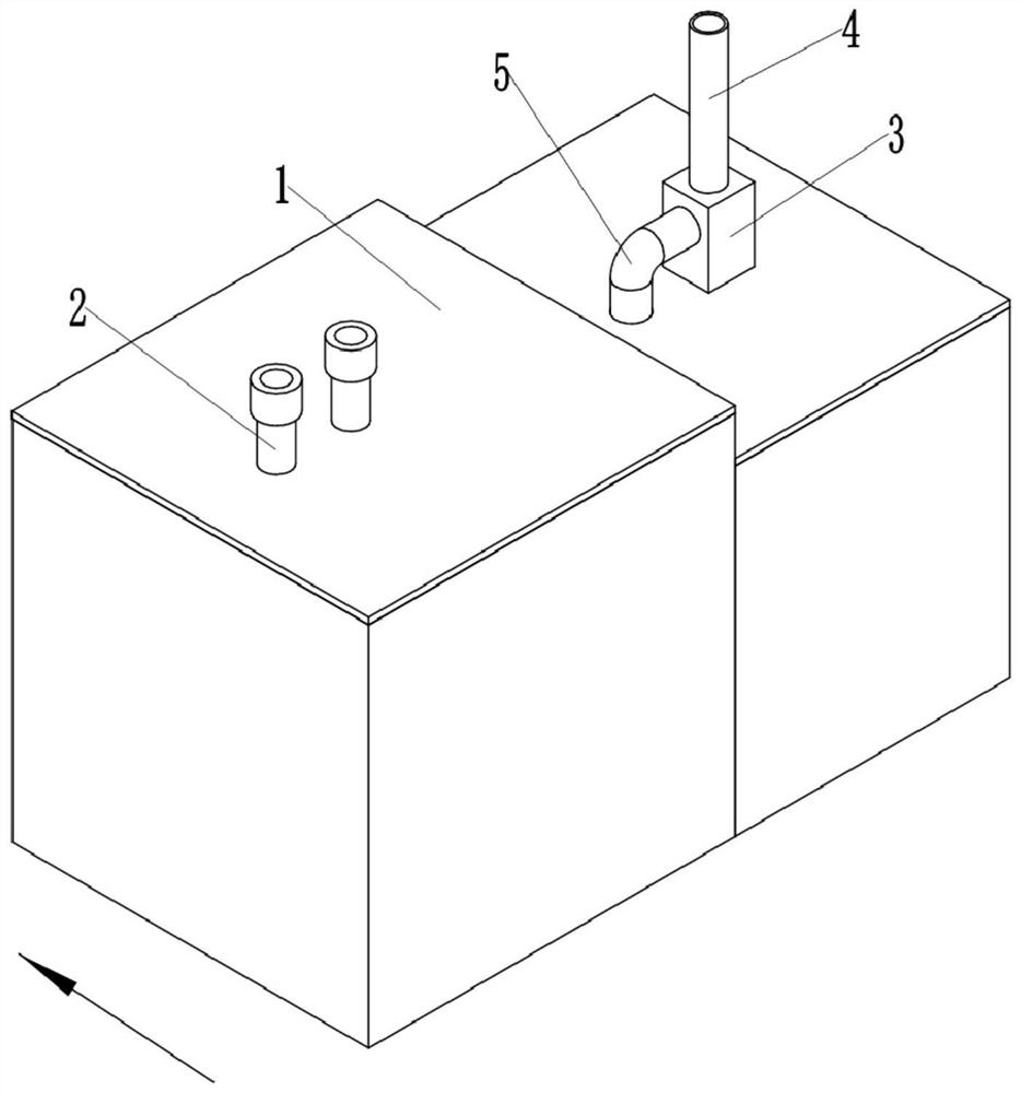
[0035] as attached figure 1 Shown: a bottle decal baking furnace, including a high-temperature furnace body 1, the high-temperature furnace body 1 is provided with an air inlet and an exhaust port, the air inlet is connected with an air inlet pipe 2, and the air inlet pipe 2 is glued inside A filter device for filtering granular impurities is fixedly provided, and the filter screen 8 is taken as an example here.
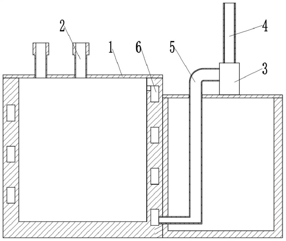
[0036] like figure 2 As shown, the side wall of the high-temperature furnace body 1 is provided with a circulation channel 6, and the circulation channel 6 is spirally arranged around the high-temperature furnace body 1. The gas outlet end of 6 is located at the lower part of the high temperature furnace body 1; the inlet end of the circulation channel 6 communicates with the interior of the high temperature furnace body 1, the gas outlet end of the circulation channel 6 communicates with the exhaust port through the exhaust pipe 5, and the exhaust port passes thro...
Embodiment 2
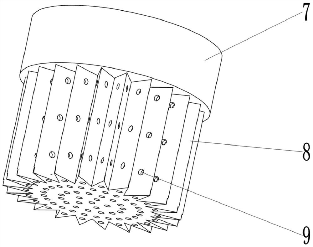
[0040]like image 3 As shown, the difference between this embodiment and Embodiment 1 is that the filter device includes a snap ring 7 and a filter screen 8 fixed to each other, the filter screen 8 is located in the middle of the snap ring 7 and completely covers the hollow part of the snap ring 7, and the filter screen 8 is a concave structure, the edge of the filter screen 8 is embedded in the snap ring 7 and fixed with the snap ring 7, and the peripheral wall of the filter screen 8 is a uniformly distributed fold shape; as Figure 4 , Figure 5 As shown, the air intake pipe 2 is provided with an installation chute 10 in the axial direction, and the snap ring 7 is slidably connected with the air intake pipe 2 through the installation chute 10 .
[0041] The snap ring 7 and the air intake pipe 2 of this program are connected through the installation chute 10, which is convenient for the installation or replacement of the filter device, and the snap ring 7 can be directly sli...
Embodiment 3
[0043] like Image 6 As shown, the difference between the present embodiment and the second embodiment is that a cylinder 11 is fixedly connected with a bolt in the chute 15, and the piston rod of the cylinder 11 is clamped and fixed with the upper end of the snap ring 7; between the snap ring 7 and the intake pipe 2 Also be provided with cleaning mechanism, cleaning mechanism comprises connecting rod 13, scraper 14 and the motor that drives connecting rod 13 to rotate, here is example with stepper motor 12, and stepper motor 12 is fixedly connected with crossbar 20 by bolt, crossbar 20 The clamping is fixedly arranged on the inner peripheral wall of the air inlet duct; the line of the stepper motor 12 is communicated with a key switch 18, and the key switch 18 is fixed on the top of the chute 15 by bolts, and the snap ring 7 can be Squeeze with the key switch 18; the output shaft of the stepper motor 12 is coaxially fixedly clamped with the connecting rod 13, and the lower en...
PUM
 Abstract
Description
Claims
Application Information
 - R&D Engineer
- R&D Manager
- IP Professional
- Industry Leading Data Capabilities
- Powerful AI technology
- Patent DNA Extraction
Browse by: Latest US Patents, China's latest patents, Technical Efficacy Thesaurus, Application Domain, Technology Topic, Popular Technical Reports.
© 2024 PatSnap. All rights reserved.Legal|Privacy policy|Modern Slavery Act Transparency Statement|Sitemap|About US| Contact US: help@patsnap.com