Preparation method of aluminum-silicon-iron alloy

A technology of ferroalloy and aluminum-silicon, which is applied in the field of preparation of aluminum-silicon-ferroalloy, can solve the problems of energy waste, high burnout rate, and high cost, and achieve the effects of reducing anode consumption, protecting anodic oxidation, and reducing heat loss

Active Publication Date: 2020-04-14
CENT SOUTH UNIV
View PDF8 Cites 0 Cited by
  • Summary
  • Abstract
  • Description
  • Claims
  • Application Information

AI Technical Summary

Problems solved by technology

Use these waste slags as raw materials for carbon electrothermal reduction to prepare aluminum-silicon alloys or aluminum-silicon-iron alloys, and then use aluminum-silicon alloys as raw materials to prepare aluminum-silicon alloys for casting. , but due to the high impurity content in the aluminum-silicon alloy and aluminum-silicon-iron alloy produced by this method, the amount used in the steelmaking process is limited, and the cost of iron removal in the process of making aluminum-silicon alloy for casting is relatively high. The economy is lower than that of ferrosilicon alloy, which limits the application of carbon electrothermal method to treat aluminum-silicon waste slag
[0005] For example, the two patents whose publication numbers are CN1328165A and CN1088622A use waste heavy oil to bond a mixture of aluminum slag powder, iron rust, silica sand, and carbon powder into a block-shaped molding, and then put it into a reaction furnace for high-temperature melting reduction. The process of preparing Al-Si alloy by this method is complicated, and the chemical composition of the prepared Al-Si-Fe alloy is unstable, which affects its use effect, causes waste of energy, and has a high burning loss rate

Method used


Image

  • Preparation method of aluminum-silicon-iron alloy
  • Preparation method of aluminum-silicon-iron alloy
  • Preparation method of aluminum-silicon-iron alloy

Examples


preparation example Construction

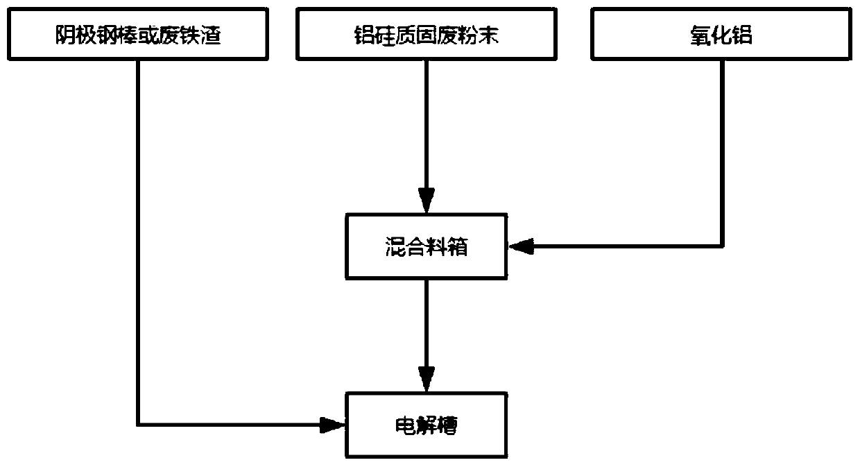
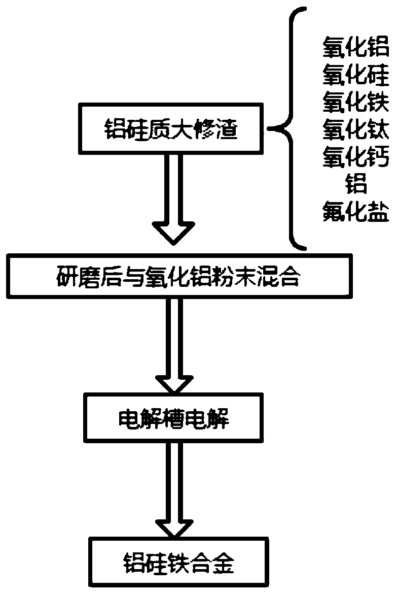
[0023] In view of the reuse of aluminum-silicon overhaul slag in the prior art, this application provides a method for preparing an aluminum-silicon alloy, which uses an electrolytic method to prepare an aluminum-silicon-iron alloy with high purity, low impurity content, and high chemical stability On the other hand, using the electrolytic cell in the aluminum electrolysis plant as the electrolytic reaction cell does not require excessive capital investment in equipment, and the electrolysis technology is mature, which solves the pollution of fluoride and cyanide in the solid waste of overhaul slag in the aluminum electrolysis industry The problem is that the harmless treatment, reduction treatment and resource treatment of the waste lining of the aluminum electrolytic cell have been realized, and the obtained Al-Si-Fe alloy is a high-value product, which has good feasibility and economy. Specifically, the preparation method of the Al-Si-Fe alloy provided by the present applica...

Embodiment 1

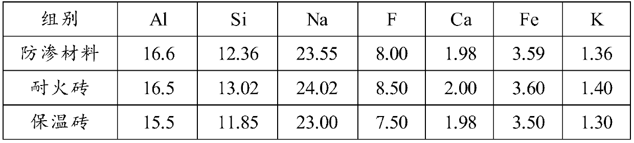
[0042] Take the aluminum-silicon solid waste in the lining of the waste tank and grind it to obtain a solid waste crushed material with a particle size of ≤0.15mm. The ground crushed material is mixed with alumina in a certain proportion, and at the same time, waste cathode steel rods (Fe content of more than 99%), during electrolysis, the waste cathode steel rods are directly thrown into the electrolytic cell to obtain a mixture; the content of aluminum in the pulverized material is 16.2wt%, the content of iron is 3.56wt%, and the content of silicon is 12.41 wt%; the weight percentage of aluminum and silicon solid waste in the mixture is 5wt%, and the quality of the steel rod is 5wt% of the mixture quality;

[0043] Add the above mixture into the electrolytic cell for electrolysis. The working voltage of the electrolytic cell is 4.028V, the electrolysis temperature is 915°C, and the current efficiency is 92.3%. The specific electrolyte is: aluminum fluoride 7.023wt%, magnesium...

Embodiment 2

[0045] Take the aluminum-silicon solid waste in the lining of the waste tank and grind it to obtain solid waste crushed material with a particle size of ≤0.15mm. Mix the ground crushed material with alumina in a certain proportion, and add the waste cathode steel rod (Fe content more than 99%) to obtain the mixture; the content of aluminum in the pulverized material is 16.2wt%, the content of iron is 3.56wt%, and the content of Si is 12.41wt%. 20wt%, the mass percentage of the waste cathode steel rod is 5wt%, and the waste cathode steel rod is directly thrown into the electrolytic cell during electrolysis;

[0046] Add the above mixture into the electrolytic cell for electrolysis. The working voltage of the electrolytic cell is 4.07V, the electrolysis temperature is 931°C, and the current efficiency is 91.2%. The specific electrolyte is: aluminum fluoride 6.524wt%, magnesium fluoride 2.153wt% , lithium fluoride 2.212wt%, calcium fluoride 3.425wt%, potassium fluoride 1.875wt%, ...


PUM

PropertyMeasurementUnit
particle diameteraaaaaaaaaa

Abstract

The invention provides a preparation method of an aluminum-silicon-iron alloy. The method comprises the following steps that: A) aluminum-silicon overhaul slag is pulverized, so that a pulverized material can be obtained, wherein the pulverized material contains 15-20wt% of aluminum, 10-15wt% of silicon and less than or equal to 5wt% of iron; and B) both or either of a waste cathode steel bar andwaste iron slag, aluminum oxide and the pulverized material are mixed, and an obtained mixture is fed into an electrolytic cell so as to be subjected to electrolysis, so that an aluminum-silicon-ironalloy can be obtained, and the superheat degree of an electrolyte for electrolysis is 10-18 DEG C. According to the method of the invention, the aluminum-silicon-iron alloy is prepared by the electrolysis method; and the aluminum-silicon-iron alloy obtained through the method is more stable in chemical property and higher in purity; and the aluminum-silicon-iron alloy is prepared from overhaul slag solid waste which is generated in the electrolytic aluminum industry and harmful to the environment, so that not only is the environmental problem of solid waste stockpiling solved, but also the solid waste is recycled, and direct economic benefits can be brought.

Description

technical field [0001] The invention relates to the technical field of reutilization of aluminum-silicon overhaul slag, in particular to a preparation method of an aluminum-silicon-iron alloy. Background technique [0002] my country is a big aluminum manufacturing country, and the output of alumina and electrolytic aluminum accounts for more than 40% of the world. High-quality bauxite resources are relatively scarce, which is far from meeting the development needs of my country's aluminum industry. More than 50% of bauxite needs to be imported, which seriously restricts the development of my country's aluminum industry. Therefore, actively exploring non-traditional aluminum minerals to produce metal aluminum and developing new aluminum smelting methods is of great significance for increasing the supply of domestic aluminum resources and promoting the sustainable development of the aluminum industry. [0003] With the continuous improvement of national environmental protect...

Claims


Application Information

Patent Timeline
Patent Type & Authority Applications(China)
IPC IPC(8): C25C3/18C22C21/00
CPCC22C21/00C25C3/18
Inventor 李贺松侯文渊崔同尧王教儒冯源孙盛林
Owner CENT SOUTH UNIV
Why Eureka
Try Eureka