
Grinding machine with clamping structure and convenient to adjust for bearing machining

A technology of clamping structure and bearing processing, applied in the direction of manufacturing tools, grinding machine bed, metal processing equipment, etc. Rotation angle and other issues to achieve the effect of reducing wear, stabilizing transportation, and slowing down the speed of descent

Inactive Publication Date: 2020-04-10
东莞市史雷帝三维数控科技有限公司
View PDF1 Cites 0 Cited by
  • Summary
  • Abstract
  • Description
  • Claims
  • Application Information

AI Technical Summary

Problems solved by technology

[0004] Aiming at the deficiencies of the prior art, the present invention provides a grinding machine with a clamping structure for easy adjustment for bearing processing, which solves the problem that the bearing rib grinding machine for bearing processing cannot collect the processed parts well in the above background technology. And the problem of not being able to collect waste chips well, and not being able to change the rotation angle of the parts well, and not being able to provide stable protection for the parts well

Method used


Image

  • Grinding machine with clamping structure and convenient to adjust for bearing machining
  • Grinding machine with clamping structure and convenient to adjust for bearing machining
  • Grinding machine with clamping structure and convenient to adjust for bearing machining

Examples


Embodiment Construction

[0027] The following will clearly and completely describe the technical solutions in the embodiments of the present invention with reference to the accompanying drawings in the embodiments of the present invention. Obviously, the described embodiments are only some, not all, embodiments of the present invention.

[0028] In the description of the present invention, unless otherwise stated, the meaning of "plurality" is two or more; the terms "upper", "lower", "left", "right", "inner", "outer" , "front end", "rear end", "head", "tail", etc. indicate the orientation or positional relationship based on the orientation or positional relationship shown in the drawings, and are only for the convenience of describing the present invention and simplifying the description, rather than Indicates or implies that the device or element referred to must have a particular orientation, be constructed and operate in a particular orientation, and therefore should not be construed as limiting the...


PUM


Abstract

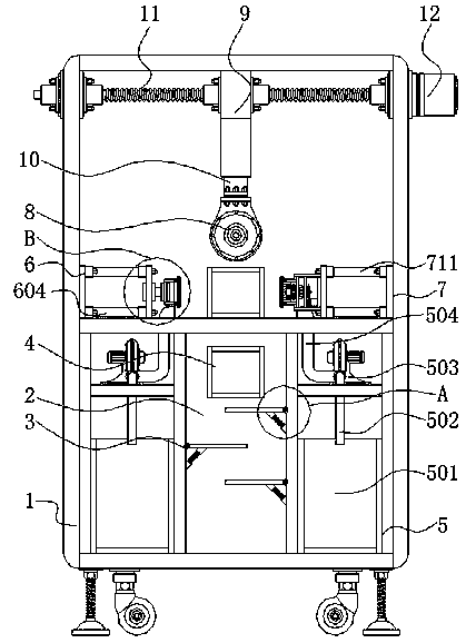
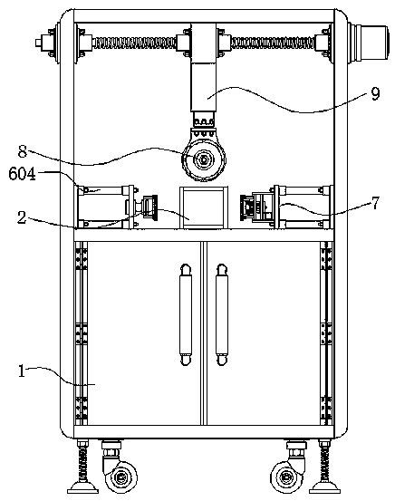
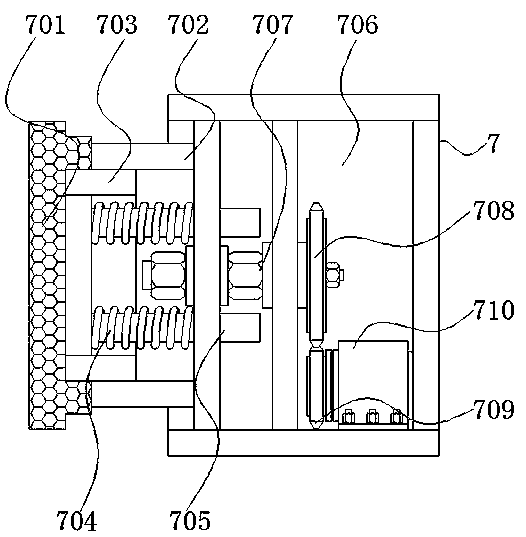
The invention discloses a grinding machine with a clamping structure and convenient to adjust for bearing machining, and the grinding machine relates to the technical field of grinding machines. Specifically, the grinding machine with the clamping structure and convenient to adjust for bearing machining comprises a bottom cabinet main frame and a scrap removing mechanism, wherein a main chamber frame is arranged in the bottom cabinet main frame; a buffer mechanism is arranged in the main chamber frame; a pipeline is mounted at the rear end of the main chamber frame; the scrap removing mechanisms are arranged on the left side and the right side of the main chamber frame; an auxiliary limiting mechanism is mounted above the bottom cabinet main frame; and a main limiting mechanism is mountedon one side of the auxiliary limiting mechanism. The grinding machine with the clamping structure and convenient to adjust for bearing machining is provided with the scrap removing mechanism, can effectively guide scraps into a scrap storage tank along the interiors of a discharge pipe and a suction pipe, collects the scraps by using the scrap storage tank in a centralized mode, and avoids the action effect of the grinding machine on parts from being affected due to the fact that the scraps accumulate in the bottom cabinet main frame.

Description

technical field [0001] The invention relates to the technical field of grinding machines, in particular to a grinding machine for bearing processing with a clamping structure for easy adjustment. Background technique [0002] Bearing ("Bearing", Japanese called "shaft receiver") is a component that fixes and reduces the friction coefficient of load during mechanical transmission. It can also be said that when other parts move relative to each other on the shaft, it is used to reduce The coefficient of friction in the process of power transmission and the parts that keep the center of the shaft fixed, the bearing is an important part in contemporary mechanical equipment. Its main function is to support the mechanical rotating body to reduce the mechanical friction of the equipment during the transmission process Load friction coefficient, according to the different friction properties of moving elements, bearings can be divided into rolling bearings and sliding bearings. Grin...

Claims


Application Information

Patent Timeline
Patent Type & Authority Applications(China)
IPC IPC(8): B24B41/00B24B41/02B24B41/06B24B47/22B24B55/06
CPCB24B41/00B24B41/02B24B41/06B24B47/22B24B55/06
Inventor 廖泽武石宏马浩鹏孙锦民
Owner 东莞市史雷帝三维数控科技有限公司
Learn More