Laser welding tinning device and welding method
A technology of laser welding and laser position, which is applied in the direction of tin feeding device, auxiliary device, welding equipment, etc., can solve the problems of abnormal welding, bumping or offset, and inability to accurately judge tin wire and solder joints, etc., to improve processing Consistency and production yield, ensure the stability of processing technology, and the effect of relative position stability
- Summary
- Abstract
- Description
- Claims
- Application Information
AI Technical Summary
Problems solved by technology
Method used
Image
Examples
Embodiment 1
[0084] Embodiment 1: SMD welding
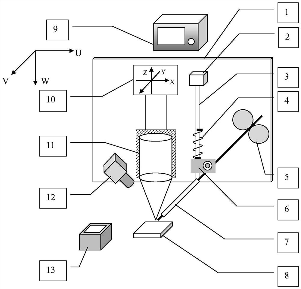
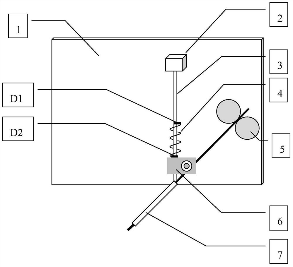
[0085] refer to Figure 4 and Figure 5 , it is necessary to ensure that the tin wire is in good contact with the solder joint during patch welding, that is, the contact force f is always kept at f during the welding process 0 , f 0 It can be selected according to the characteristics of tin wire and welding process. In the positioning stage, when the contact force between the tin wire and the pad is at f b When within the range of ±Δf, stop positioning immediately. During the welding process, the pushing speed of the tin wire is adjusted by the PID algorithm. When the tin tip is not melted, if the tin is continuously fed, the contact force f between the tin wire and the pad will increase, and the tin feeding speed should be reduced at this time; When the wire melts too fast, the contact force f between the tin wire and the pad decreases, and the tin feeding speed should be accelerated at this time.
Embodiment 2
[0086] Embodiment 2: pin welding
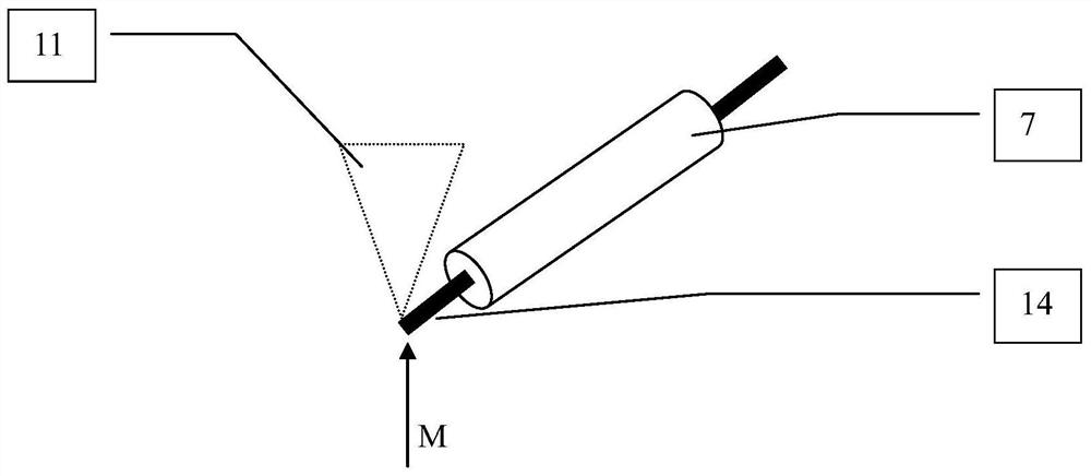
[0087] refer to Figure 4 and Figure 6 , when the pin pin 15 is deformed, in the positioning stage of the probe head 14, the tin tip 16 will be deflected to the right after contacting the top of the pin 15, and the angle sensor 2 records the deflection angle of the tin wire 14, but at this time the balance spring 4 The vertical contact force is 0, so the device continues to move downward. During the movement, under the restoring force of the balance spring 4, the tin tip 16 is always in contact with the contact pin 15 until the contact force f is within f b within the range of ±Δf. During the contact process between the tin tip 16 and the contact pin 15, the running track of the tin tip 16 is close to the shape of the contact pin 15, such as Figure 6 As shown, the tin tip 16 can effectively avoid the interference of the pin pin 15 and be accurately positioned to the pad 8 to be soldered.
[0088] The invention utilizes the position fee...
PUM
 Abstract
Description
Claims
Application Information
 - R&D
- Intellectual Property
- Life Sciences
- Materials
- Tech Scout
- Unparalleled Data Quality
- Higher Quality Content
- 60% Fewer Hallucinations
Browse by: Latest US Patents, China's latest patents, Technical Efficacy Thesaurus, Application Domain, Technology Topic, Popular Technical Reports.
© 2025 PatSnap. All rights reserved.Legal|Privacy policy|Modern Slavery Act Transparency Statement|Sitemap|About US| Contact US: help@patsnap.com


