
Method for constructing cement soil underground continuous wall under complex geological condition

A technology of complex geological conditions and underground diaphragm walls, applied in sheet pile walls, infrastructure engineering, earth movers/shovels, etc., can solve the problems of difficult cutting, large equipment wear, slow construction progress, etc., to save cutting The effect of time, surface leveling, and reduction of construction difficulty

Inactive Publication Date: 2020-04-03
天津市津勘岩土工程股份有限公司
View PDF2 Cites 7 Cited by
  • Summary
  • Abstract
  • Description
  • Claims
  • Application Information

AI Technical Summary

Problems solved by technology

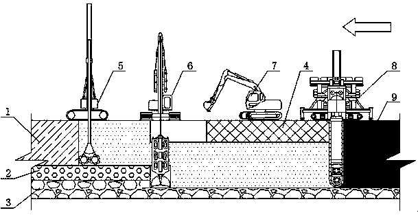
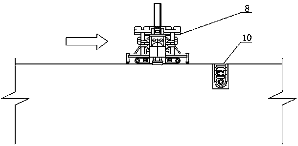
[0006] The purpose of the present invention is to provide a construction method for the diaphragm wall under cement land with complex geological conditions, which adopts the combination of milling and grasping, that is, adopts double-wheel milling and deep stirring equipment to cut the soil layer above the gravel soil layer, and its construction verticality can reach 3‰, play a guiding role for the construction of the grab bucket of the underground diaphragm wall trough forming machine, and then use the grab bucket of the underground diaphragm wall trough forming machine to clean up large-sized gravel and soil and enter the impermeable layer. After the construction of the grab bucket, a continuous open slot is formed Finally, use TRD equipment to mix and grout to form a cement-soil continuous wall, so as to solve the problems of the existing TRD construction method in the high-strength and dense gravel soil layer, difficult cutting, slow construction progress, and large equipment wear.

Method used


Image

  • Method for constructing cement soil underground continuous wall under complex geological condition
  • Method for constructing cement soil underground continuous wall under complex geological condition
  • Method for constructing cement soil underground continuous wall under complex geological condition

Examples


Embodiment

[0031] A specific application of the construction method of the diaphragm wall under cement soil under complex geological conditions of the present invention in the construction of a residential area. The residential area around the residential area has been built with a relatively high density residential area. The original construction stratum is divided into three depths from top to bottom. The first depth is mainly composed of cohesive soil, silt and sandy soil; the second depth is mainly composed of gravel soil; the third depth is mainly composed of impermeable layers 3 such as strongly weathered conglomerate and cohesive soil. The shape of the underground diaphragm wall is similar to "L", and the foundation pit adopts the support form of inserting H-shaped steel in the diaphragm wall under the cement soil with a thickness of 800mm and adding 1 to 2 rotary grouting anchor rods. The excavation depth of the foundation pit is 6.91-10.16m, the construction depth is 18.5m, and ...


PUM


Abstract

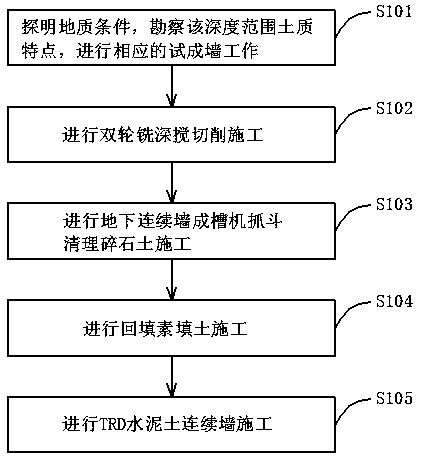
The invention relates to the technical field of building engineering, in particular to a method for constructing a cement soil underground continuous wall under a complex geological condition. The method aims to solve the problems of difficult cutting, slow construction progress, large equipment wear and the like of an existing TRD working method in a high-strength dense gravel land layer. The method comprises the specific steps that the geological condition is explored, the characteristics of the soil within the depth range are surveyed, and corresponding test wall forming work is carried out; double-wheel milling deep stirring cutting construction is carried out; gravel soil cleaning construction is carried out by an underground continuous wall grooving machine grab bucket; plain fill backfill construction is carried out; and TRD cement soil continuous wall construction is carried out. The method for constructing the cement soil underground continuous wall under the complex geological condition has the beneficial effects of avoiding equipment losses, saving cutting time, reducing cement soil continuous wall construction difficulty, improving construction quality and constructionefficiency and the like.

Description

technical field [0001] The invention belongs to the technical field of construction engineering, and in particular relates to a construction method for a diaphragm wall under cement soil under complex geological conditions. Background technique [0002] The TRD construction method was developed by Japan in the early 1990s. It is a complete set of equipment and construction method that can continuously form walls in various soil layers and sand and gravel layers. The basic principle is to use the chain saw tool box to insert vertically into the ground, and then move horizontally and horizontally. At the same time, the chain drives the tool to make up and down rotary motions, stir and mix the original soil and pour cement slurry and other consolidation slurry to form a certain thickness. the wall. Its main features are continuous wall formation, smooth surface, consistent thickness, and good wall uniformity. It is mainly used in various construction projects, underground pro...

Claims


Application Information

Patent Timeline
Patent Type & Authority Applications(China)
IPC IPC(8): E02D5/18E02F3/10E02F3/14
CPCE02D5/187E02F3/10E02F3/142E02F3/144
Inventor 曾建华陈德亮朱进运桂红闫玲胡正亮王洪涛焦文智李建显董学辉闫华云陈强肖遥孙世龙赵鹏尚志明
Owner 天津市津勘岩土工程股份有限公司
Learn More