Heat exchanger and condensing boiler

A technology for heat exchangers and heat exchange tubes, applied in the field of boilers, can solve problems such as difficulties in heat exchanger design, processing, and mass production, increase in material use costs and processing costs, and slow progress in the transformation process of condensation technology, achieving reduction probability, lower flue gas temperature, and improve heat transfer effect

Pending Publication Date: 2020-03-27
VALPO ENERGY & ENVIRONMENT TECH CO LTD +1
View PDF0 Cites 1 Cited by
  • Summary
  • Abstract
  • Description
  • Claims
  • Application Information

AI Technical Summary

Problems solved by technology

[0002] Condensing boilers have the characteristics of high efficiency, energy saving and environmental protection, and are the development direction of the boiler industry. At present, the technology of small condensing boilers or gas condensing water heaters has gradually matured, but due to the difficulties in the design, processing, and mass production of heat exchangers, condensing technology has become increasingly popular. Slow progress in large commercial boiler conversion process
[0003] Existing condensing boilers can generally be divided into stainless steel and cast aluminum boilers according to their materials. Since condensing boilers require a large heat exchange area, stainless steel condensing boilers generally use finned tubes as heat exchange elements as much as possible. At the same time, in order to improve The heat transfer effect will also be improved by bending the finned tubes to enhance the heat transfer. The above two solutions increase the cost of material use and processing costs, and at the same time affect production efficiency
Furthermore, when a finned tube is damaged and needs to be replaced, it will also increase the material cost and processing cost

Method used


Image

  • Heat exchanger and condensing boiler
  • Heat exchanger and condensing boiler
  • Heat exchanger and condensing boiler

Examples


Embodiment

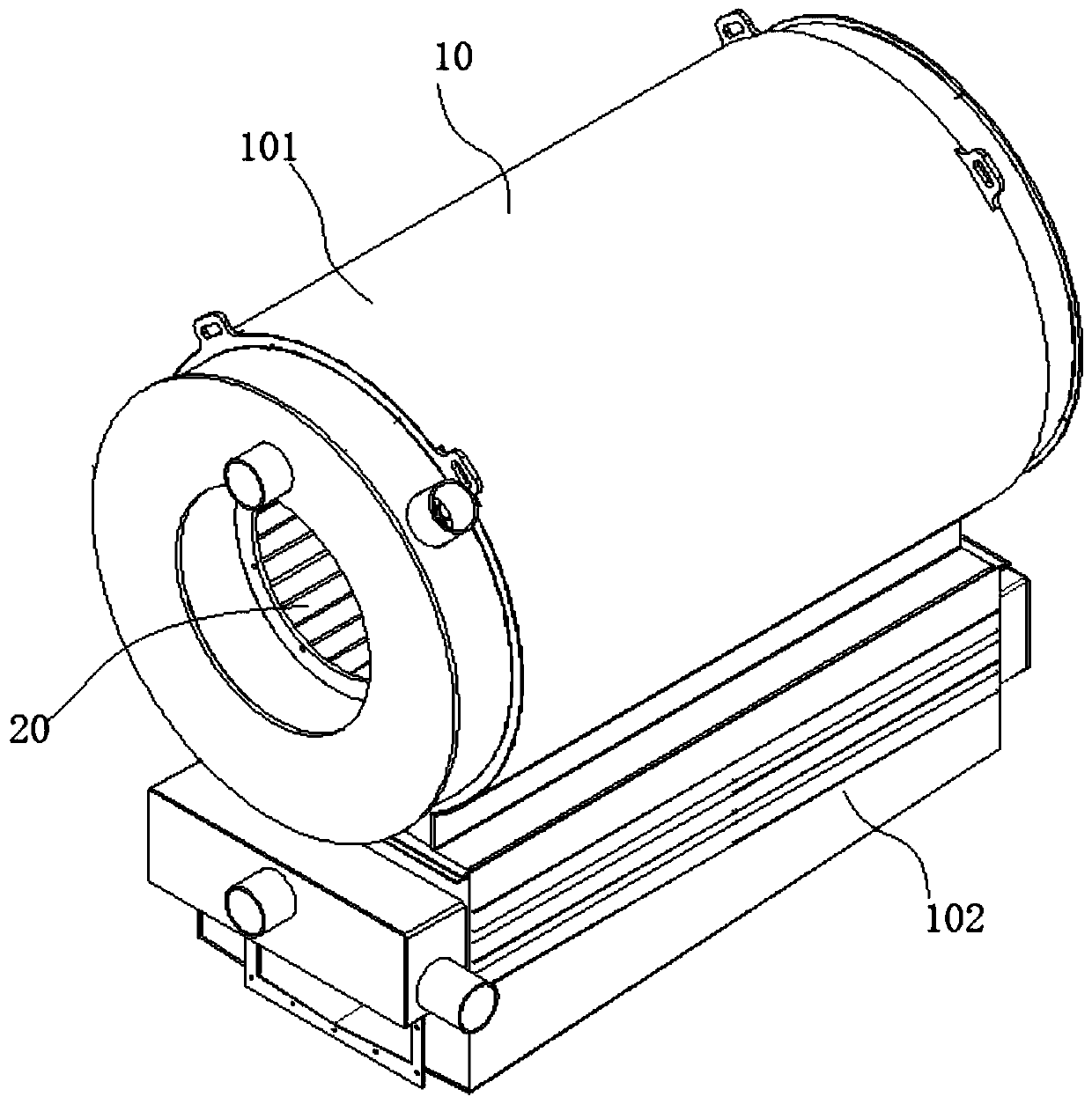
[0050] see Figure 1 to Figure 9 , figure 1 is a schematic structural view of a condensing boiler provided by an embodiment of the present invention;

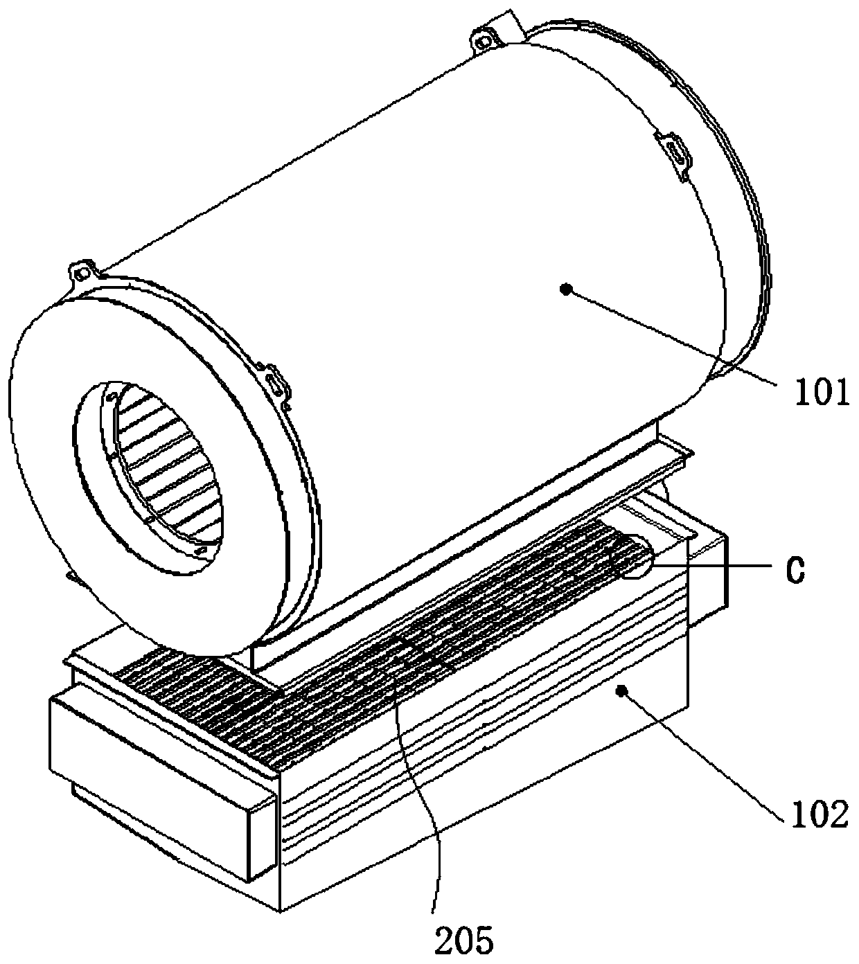
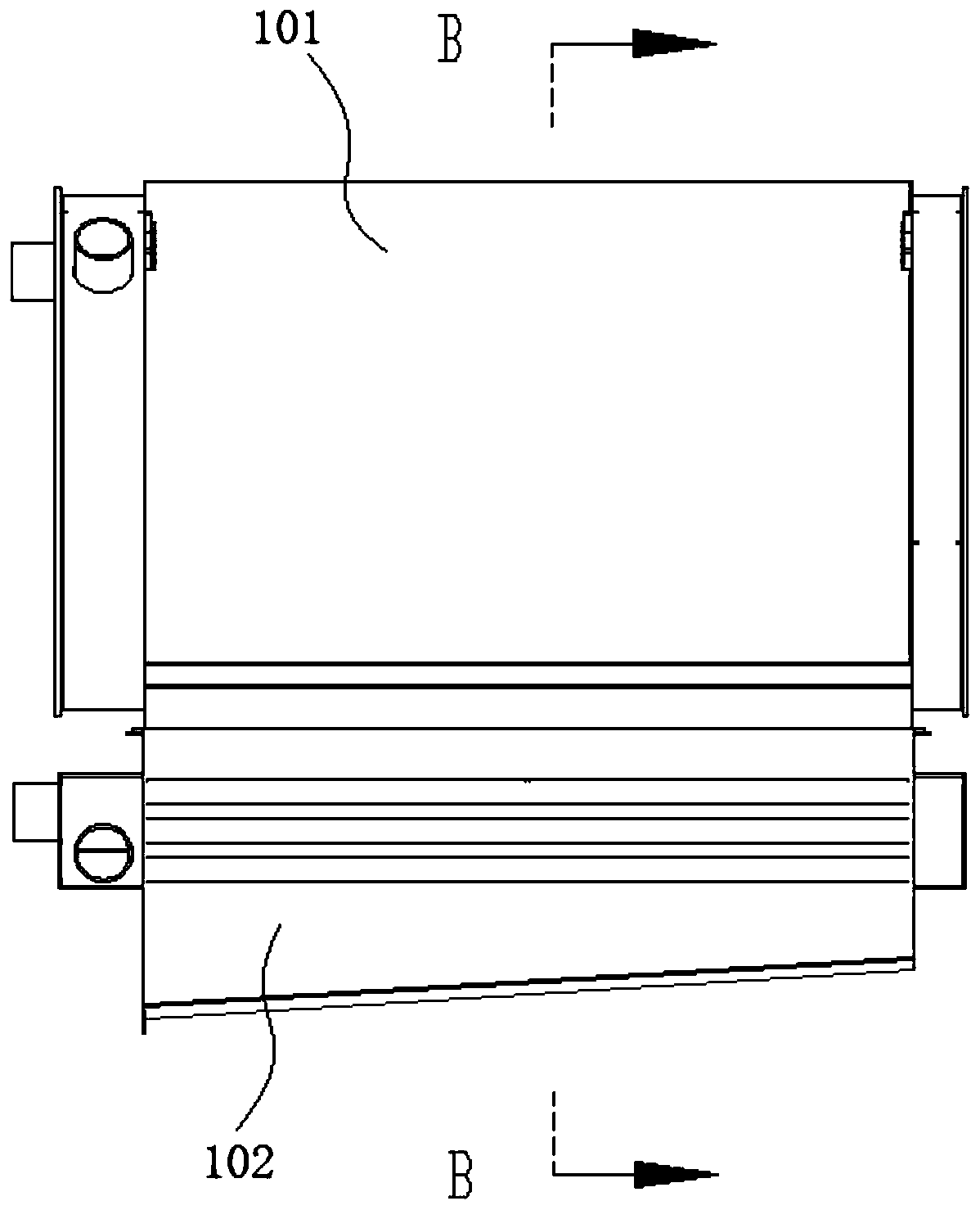
[0051] figure 2 yes figure 1 Schematic diagram of the separation of the upper and lower structures; image 3 yes figure 1 The schematic diagram of the main view; Figure 4 yes image 3 Right view diagram; Figure 5 yes image 3 The left view schematic diagram of ; Figure 6 yes Figure 5 A schematic cross-sectional view of A; Figure 7 yes image 3 B-direction cross-sectional schematic diagram; Fig. 8(a) is figure 2 Figure 8(b) is a schematic diagram of the cross-sectional structure of the outer heat exchange tube of the present invention in an embodiment; Figure 8(c) is an embodiment of the inner heat exchange tube of the present invention Schematic diagram of the cross-sectional structure in the example; Figure 9 yes figure 2 The enlarged schematic diagram of the second deflector in the middle.

[0052] like...


PUM


Abstract

The invention provides a heat exchanger and a condensing boiler. The heat exchanger includes an inner heat exchange tube and an outer heat exchange tube located on an outer ring of the inner heat exchange tube. The inner heat exchange tube has a receiving cavity. The direction of the central axis of the receiving cavity is consistent with the directions of the central axes of the inner and outer heat exchange tubes. The inner and outer heat exchange tubes are both light tubes. The heat exchanger has high heat exchange efficiency and is beneficial to a high-power boiler.

Description

technical field [0001] The invention relates to the technical field of boilers, in particular to a heat exchanger and a condensing boiler. Background technique [0002] Condensing boilers have the characteristics of high efficiency, energy saving and environmental protection, and are the development direction of the boiler industry. At present, the technology of small condensing boilers or gas condensing water heaters has gradually matured, but due to the difficulties in the design, processing, and mass production of heat exchangers, condensing technology has become increasingly popular. The conversion process for large commercial boilers has been slow. [0003] Existing condensing boilers can generally be divided into stainless steel and cast aluminum boilers according to their materials. Since condensing boilers require a large heat exchange area, stainless steel condensing boilers generally use finned tubes as heat exchange elements as much as possible. At the same time, ...

Claims


Application Information

Patent Timeline
Patent Type & Authority Applications(China)
IPC IPC(8): F24H8/00F24H9/00
CPCF24H8/00F24H9/0005Y02B30/00
Inventor 崔树庆叶昕殷海鹏徐斌
Owner VALPO ENERGY & ENVIRONMENT TECH CO LTD
Why Eureka
Try Eureka