


Quick Research
Generate reliable direction feasibility study reports for your R&D in just a few steps.

Technical Q&A
Discover and master advanced knowledge NOW. Basics, ideas, possibilities, all at once.

Find Solutions
As an expert in R&D theories, this can generate solutions to your technical problems instantly.

Evaluate Feasibility
Analyze your overall solution with one click, know your potential R&D risks in advance.

Monitor Landscape
Get weekly tech updates, stay abreast of the latest tech innovations and key insights.
Grinding device for processing parts of railway locomotives and vehicles
A technology for railway locomotives and vehicles, which is applied in the direction of grinding drive devices, grinding/polishing safety devices, metal processing equipment, etc., and can solve problems such as easy blockage of slide rail installation grooves and inconvenient operation
- Summary
- Abstract
- Description
- Claims
- Application Information
AI Technical Summary
Problems solved by technology
Method used
Image

Examples
Embodiment 1
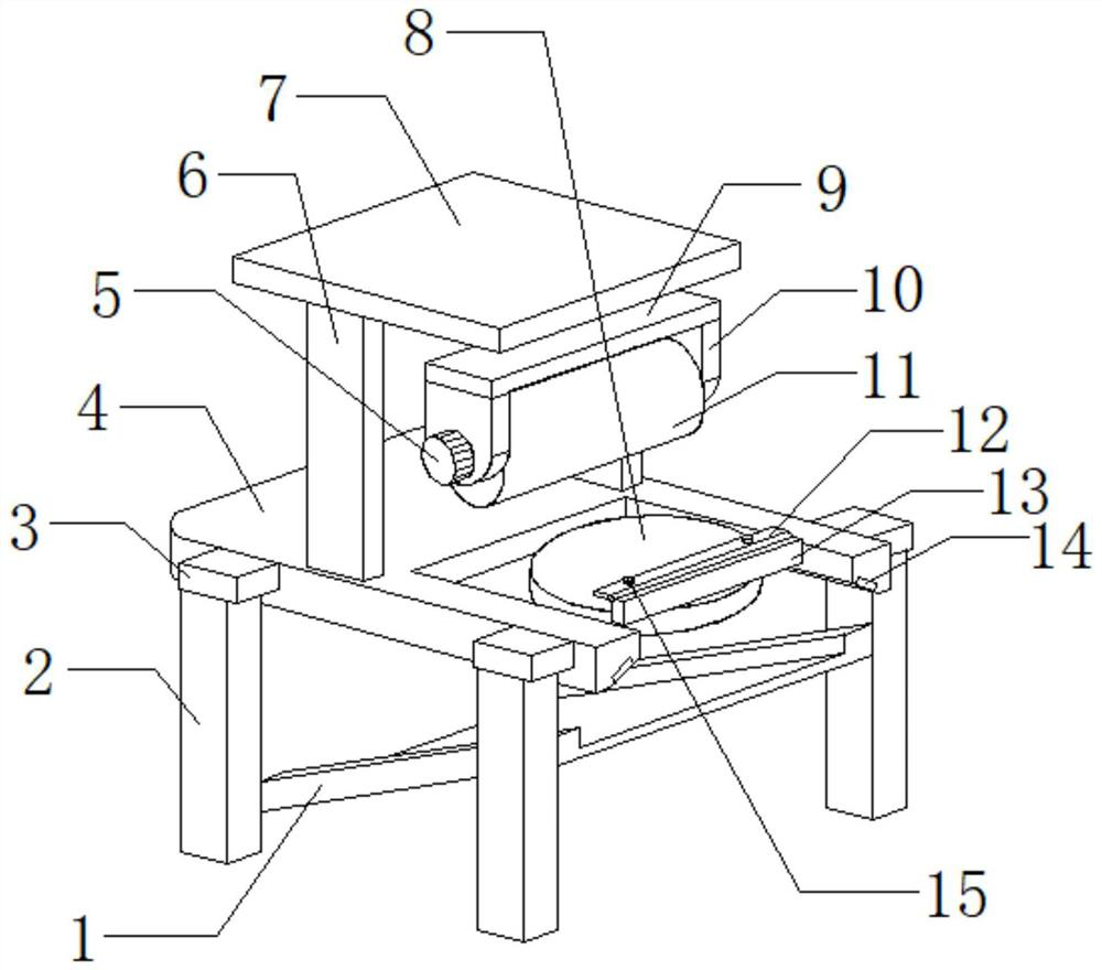
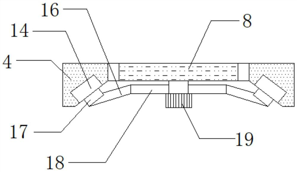
[0028] refer to Figure 1-3 , a grinding device for processing parts of railway locomotive vehicles, comprising a supporting platform 4 and four supporting legs 2, the outer walls on both sides of the supporting platform 4 are connected with connecting plates 3 by bolts, and the four supporting legs 2 are respectively connected by bolts Installed on the bottom outer walls of the four connecting plates 3, the outer wall on one side of the support platform 4 is provided with a first groove, and the bottom outer walls at both ends of the first groove are provided with oblique grooves, and the inner walls of the two oblique grooves pass through Bolts are connected with electric guide rails 14, and the bottom outer walls of the two electric guide rails 14 are slidingly connected with electric sliders 17. The bottom outer walls of the two electric sliders 17 are connected with connecting rods 16 by bolts, and the two connecting rods 16 pass The bolt is connected with the third suppo...
Embodiment 2
[0033] refer to figure 1 , 2 And 4, a grinding device for railway locomotive and vehicle parts processing, also includes a water storage tank 25 installed on the outer wall of the other side of the top of the support top plate 7 by bolts, and the outer wall of the top side of the water storage tank 25 is connected with a water inlet pipe by bolts 24. The outer wall at the top of the circumference of the water inlet pipe 24 is threadedly connected to the water inlet pipe cover, the outer wall on the other side of the bottom of the water storage tank 25 is connected to the water guide pipe 26 through bolts, and the bottom outer wall on one side of the circumference of the water guide pipe 26 is connected to a suction pipe through bolts. The water pump 27, the bottom outer wall of the water guide pipe 26 is connected with the water guide hose 23 by bolts, and the bottom outer wall of the water guide hose 23 is connected with the water distribution pipe 22 by bolts, and one side o...
PUM
 Abstract
Description
Claims
Application Information
 - R&D Engineer
- R&D Manager
- IP Professional
- Industry Leading Data Capabilities
- Powerful AI technology
- Patent DNA Extraction
Browse by: Latest US Patents, China's latest patents, Technical Efficacy Thesaurus, Application Domain, Technology Topic, Popular Technical Reports.
© 2024 PatSnap. All rights reserved.Legal|Privacy policy|Modern Slavery Act Transparency Statement|Sitemap|About US| Contact US: help@patsnap.com