Al technical title is built by PatSnap Al team. It summarizes the technical point description of the patent document.
A slitting machine and a new type of technology, applied in shearing machine equipment, shearing devices, accessories of shearing machines, etc., can solve the problems of running knife, inaccurate width of cut material, and different diameters of steel strips. Achieve the effect of meeting cutting requirements, easy to pack and store, and accurate material width
Active Publication Date: 2020-03-24
重庆兰羚天和科技股份有限公司
View PDF6 Cites 0 Cited by
Summary
Abstract
Description
Claims
Application Information
AI Technical Summary
This helps you quickly interpret patents by identifying the three key elements:
Problems solved by technology
Method used
Benefits of technology
Problems solved by technology
[0004]
(1) During the dragging and leveling process of the existing slitting machine, since the transmission device can only guide the strip steel left and right, but the up and down directions cannot be restricted, when the strip steel material is conveyed at a high speed, up and down vibrations will occur , resulting in the phenomenon of "knife running", resulting in inaccurate width of the cut material, which cannot meet the cutting requirements
[0005]
(2) The existing slitting machine does not have a device for fiber in the winding device, which may easily cause the diameter of the steel strip to be wound to be different, and it is not easy to store
[0006]
(3) It is impossible to detect whether there are defects on the steel plate raw materials; the strip steel after winding is inconvenient to pack
Method used
Image
Click on the blue label to locate the original text in one second.
Reading with bidirectional positioning of images and text.
Examples
Embodiment Construction
[0036] In order to further understand the content, features and effects of the present invention, the following examples are given, and detailed descriptions are given below with reference to the accompanying drawings.
[0037] Aiming at the problems existing in the prior art, the present invention provides a novel slitting machine system. The present invention will be described in detail below in conjunction with the accompanying drawings.
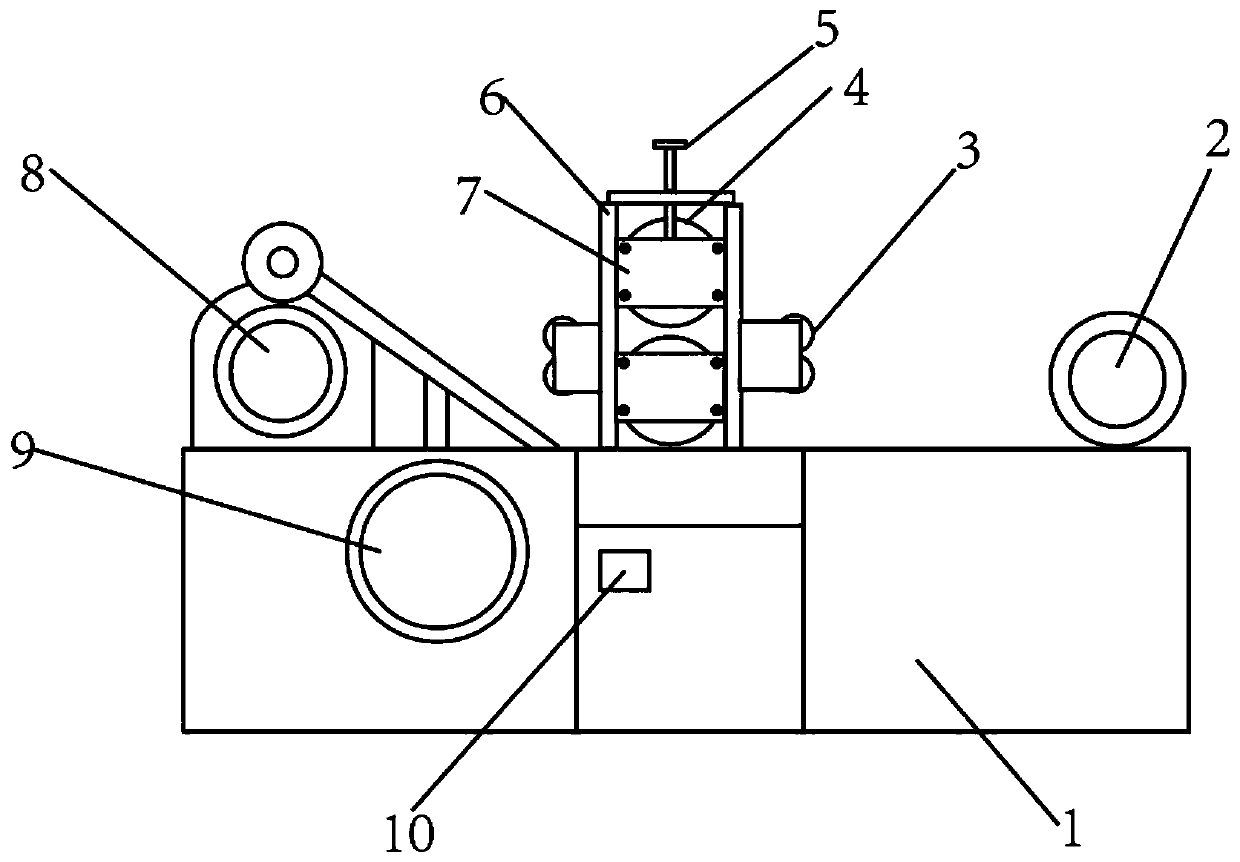
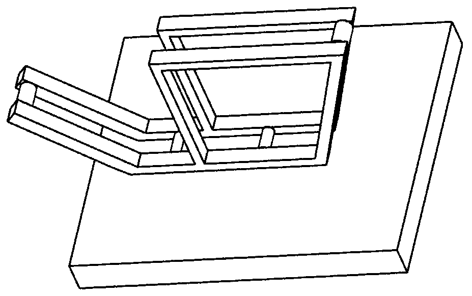
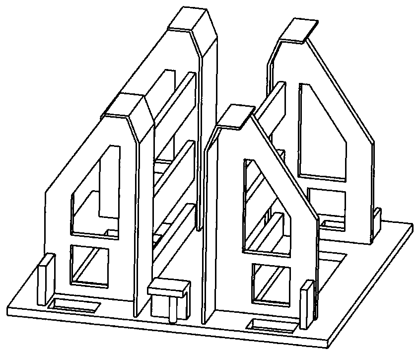
[0038] like Figure 1 to Figure 5 As shown, a new type of slitting machine system includes a base 1, an uncoiler 2 is arranged at the right end of the base 1; a slitting machine detection module 10 is arranged on the front side of the middle part, and a bracket 6 and a slitting machine are installed on the upper side through bolts. Gear wheel, the middle part of the support 6 is provided with two cutter shafts 4 up and down, blades are installed on the shaft, and the left and right sides of the support 6 are sequentially installed with ro...
PUM
Abstract
The invention belongs to the technical field of metal processing and discloses a novel slitting machine system. The system comprises a base, wherein an uncoiler is arranged at a right end of the base,a slitting machine detection module is arranged on a front side of the middle, a support and a slitting gear wheel are installed on an upper side through bolts, two cutter shafts are vertically arranged in the middle of the support in sequence, blades are installed on the cutter shafts, rotating shafts are vertically and sequentially installed on the left side and the right side of the support through bolts, carrier rollers are fixedly connected with the rotating shafts, a flattening device is arranged at a left end of the base, a lower right corner of the flattening device is only provided with a winding device on a front side of the base, and an outer side of the winding device is sleeved with a plastic sleeve. The system is advantaged in that through a carrier roller structure, vertical vibration of steel material conveying is reduced, and a phenomenon of tool shifting cannot be caused; limiting is conducted through the thickness of a plurality of rolled steel strips by means of aplastic sleeve on an outer side of the winding device, so the rolled steel strips are consistent in diameter and easy to store; by arranging pipe coil packing belt scissors and a longitudinal shearingpacking storage device, the sheared strip steels are easy to pack and store.
Description
technical field [0001] The invention belongs to the technical field of metal processing, in particular to a novel slitting machine system. Background technique [0002] At present, the closest existing technology: slitting machine is also called slitting line, slitting machine, and slitting machine, which is a kind of appellation for metal slitting equipment. It is suitable for longitudinal cutting of metal strips, and rewinds the narrow strips into rolls. It has the characteristics of convenient operation, high cutting quality, high material utilization rate, and stepless speed regulation of cutting speed. (unwinding), guide material positioning, slitting, coiling (rewinding) and other components, suitable for tinplate, silicon steel sheet, aluminum strip, copper, stainless steel plate, galvanized plate and other materials, widely used in transformers, motors, Household appliances, automobiles, building materials, packaging and other industries. During the dragging and le...
Claims
Application Information
Patent Timeline
Application Date:The date an application was filed.
Publication Date:The date a patent or application was officially published.
First Publication Date:The earliest publication date of a patent with the same application number.
Issue Date:Publication date of the patent grant document.
PCT Entry Date:The Entry date of PCT National Phase.
Estimated Expiry Date:The statutory expiry date of a patent right according to the Patent Law, and it is the longest term of protection that the patent right can achieve without the termination of the patent right due to other reasons(Term extension factor has been taken into account ).
Invalid Date:Actual expiry date is based on effective date or publication date of legal transaction data of invalid patent.