
Hardware punching device

A punching device and hardware technology, applied in the direction of feeding device, positioning device, storage device, etc., can solve the problems of reduced practicability, hardware deformation, uneven pressure, etc., and achieves fast punching process and small deformation. , the effect of improving usability

Inactive Publication Date: 2020-03-24
盐城瑞嘉汽车服务有限公司
View PDF6 Cites 0 Cited by
  • Summary
  • Abstract
  • Description
  • Claims
  • Application Information

AI Technical Summary

Problems solved by technology

The formed hardware parts are transported to retail stores for sale. Most of the hardware parts are standard parts, but they are not necessarily suitable for the actual use requirements of buyers. Therefore, the retail stores need to perform secondary processing, punching and other processing on the hardware parts. The traditional operation method It is the operator who directly puts the hardware on the ground, uses the punching tool for secondary processing, or uses the electric hand drill to punch the hole. Due to the uneven pressure of this kind of processing process, it may lead to Cause hardware deformation, damage hardware, and reduce practicability

Method used


Image

  • Hardware punching device
  • Hardware punching device
  • Hardware punching device

Examples


Embodiment Construction

[0019] The specific implementation manners of the present invention will be further described in detail below in conjunction with the accompanying drawings and embodiments. The following examples are used to illustrate the present invention, but are not intended to limit the scope of the present invention.

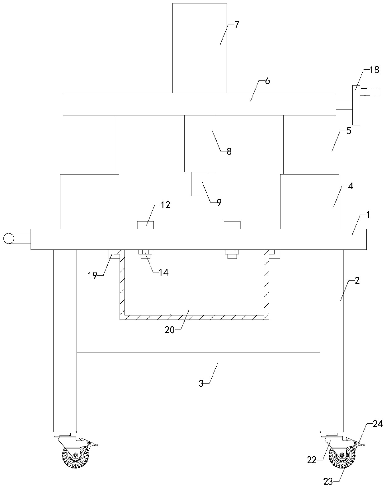
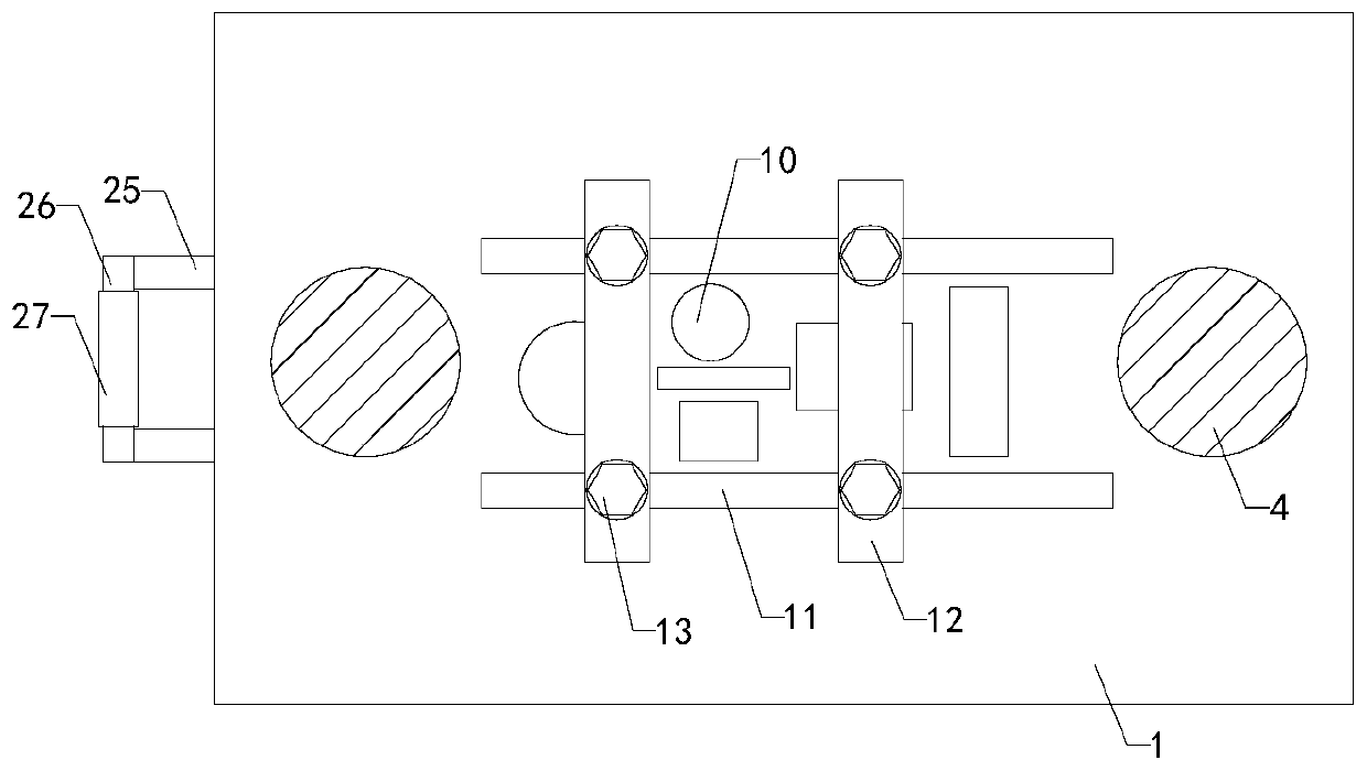
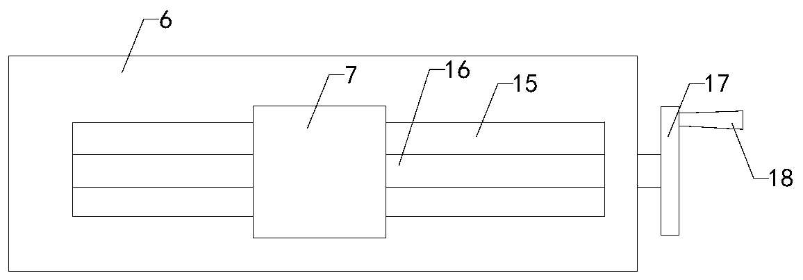
[0020] Such as Figure 1 to Figure 5 As shown, a hardware punching device of the present invention includes a workbench 1, a hydraulic cylinder piston 5, a cylinder 7, a cylinder piston 8, a punching hole 10, a sliding platen 12, countersunk head bolts 13 and nuts 14, and the workbench 1 The four corners of the bottom end are respectively provided with supporting legs 2, the top of the supporting legs 2 is connected to the bottom of the workbench 1, and a reinforcing beam 3 is arranged between the two sets of supporting legs 2, and the two ends of the reinforcing beam 3 are respectively connected to the inner sides of the two sets of supporting legs 2, Two sets of hydraul...


PUM


Abstract

The invention relates to the machining equipment technology field and especially relates to a hardware punching device. The device is used for fixing hardware firstly and then carrying out stamping secondary machining on the hardware through a stamping device. Compared with a traditional handheld stamping tool, the hardware punching device is more convenient to use, a stamping process is fast, a hardware deformation amount is small, and practicability is improved. The punching device comprises a workbench, a hydraulic cylinder piston, an air cylinder, an air cylinder piston, a punched hole, asliding pressing plate, a countersunk bolt and a nut. Supporting legs are arranged at four corners of a bottom end of the workbench. Top ends of the supporting legs are connected with a bottom end ofthe workbench. The bottom end of the countersunk bolt penetrates through a through hole in a bottom end of a sliding pressing plate to extend to the bottom end of the workbench so as to be connected with the nut in a matched mode, the sliding pressing plate can slide to the left and to the right in a sliding groove, the sliding pressing plate and the sliding groove can be fixed by rotating the countersunk bolt, the sliding pressing plate cannot slide on the sliding groove, and hardware can be placed at the top end of the workbench and is fixed through the sliding pressing plate.

Description

technical field [0001] The invention relates to the technical field of mechanical processing equipment, in particular to a hardware punching device. Background technique [0002] Hardware parts refer to products obtained by processing and casting gold, silver, copper, iron, tin and other metals. In the process of manufacturing hardware parts, stamping is generally used to manufacture hardware parts. The high-strength hydraulic device performs pressure impact and completes stamping. The formed hardware parts are transported to retail stores for sale. Most of the hardware parts are standard parts, but they are not necessarily suitable for the actual use requirements of buyers. Therefore, the retail stores need to perform secondary processing, punching and other processing on the hardware parts. The traditional operation method It is the operator who directly puts the hardware on the ground, uses the punching tool for secondary processing, or uses the electric hand drill to pu...

Claims


Application Information

Patent Timeline
Patent Type & Authority Applications(China)
IPC IPC(8): B21D28/24B21D43/00B21D43/20
CPCB21D28/24B21D43/003B21D43/20
Inventor 苏萍陈璐葛艳虹
Owner 盐城瑞嘉汽车服务有限公司
Learn More