Quantum dot light emitting diode
A quantum dot light-emitting and diode technology, which is applied in nanotechnology, electrical components, nanotechnology, etc., can solve the problems of low device efficiency and service life, and achieve the effects of improving service life, reducing operating voltage and improving electron transmission
- Summary
- Abstract
- Description
- Claims
- Application Information
AI Technical Summary
Problems solved by technology
Method used
Image
Examples
Embodiment 1
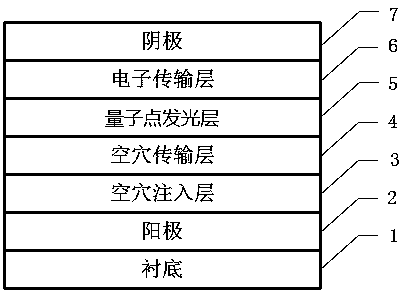
[0343] Example 1: 1) The quantum dot light-emitting diode structure includes a glass substrate, an ITO anode, a hole injection layer, a 35nm hole transport layer, a 20nm quantum dot light emitting layer, and a 40 nm electron transport layer arranged in sequence from bottom to top and 100nm cathode. The surface ligands of the quantum dot light-emitting layer are octadecylphosphoric acid and Cl - CdZnS / ZnS quantum dot layer with mixed ligands. The preparation method of the quantum dot light-emitting diode device is as follows:
[0344] 2) A hole injection layer and a 35 nm hole transport layer are coated sequentially on the ITO bottom electrode.
[0345] 3) Using surface ligands as stearyl phosphate and Cl - A heptane solution of CdZnS / ZnS quantum dots mixed with ligands was used to form a 20nm quantum dot light-emitting layer on the hole transport layer using a spin-coating method with a rotation speed of 2000rpm.
[0346] 4) Spin-coat the ZnO methanol solution on the quant...
Embodiment 2
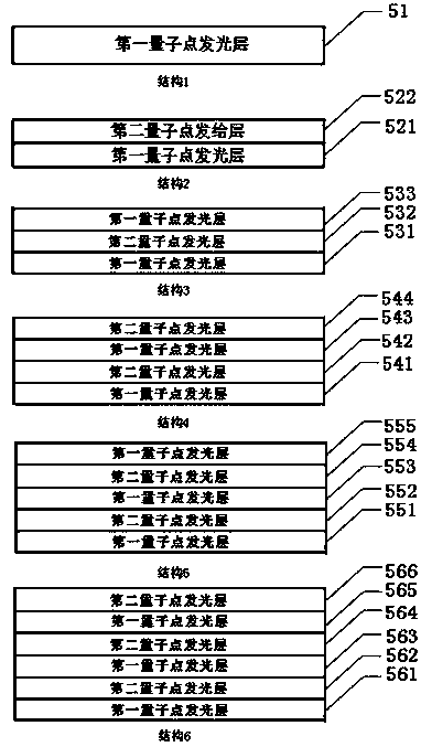
[0349] Example 2: 1) The quantum dot light emitting diode structure includes a glass substrate, an ITO anode, a hole injection layer, a 35nm hole transport layer, a 40nm quantum dot light emitting layer, and a 50 nm electron transport layer arranged in sequence from bottom to top and 100nm cathode. The quantum dot luminescent layer is a CdZnSe / ZnSe quantum dot layer and a polar CdZnSe / ZnSe quantum dot luminescent layer whose surface ligands are mixed ligands of octadecylphosphoric acid and 3-mercaptopropionic acid, and each layer is 20nm. The preparation method of the quantum dot light-emitting diode device is as follows:
[0350] 2) A hole injection layer and a 35 nm hole transport layer are coated sequentially on the ITO bottom electrode.
[0351] 3) Using 20 mg / ml of luminescent quantum dot heptane solution, on the hole transport layer, use a spin-coating method with a rotation speed of 2000 rpm to form a CdZnSe / CdZnSe with octadecylphosphoric acid and 3-mercaptopropionic ...
Embodiment 3
[0355] Example 3: 1) The quantum dot light-emitting diode structure includes a glass substrate, an ITO anode, a hole injection layer, a 20 nm hole transport layer, a 30 nm quantum dot light emitting layer, and a 60 nm electron layer arranged in sequence from bottom to top. Transport layer and 80 nm cathode. The surface ligands of the light-emitting layer are octylthiol and Br - Mixed ligand CdZnSe / ZnSe quantum dot layer, polar CdZnSe / ZnSe quantum dot light-emitting layer, surface ligands are octylthiol and Br - Mixed ligand CdZnSe / ZnSe quantum dot layer, each layer 10nm. The preparation method of the quantum dot light-emitting diode device is as follows:
[0356] 2) A hole injection layer and a 20 nm hole transport layer are coated sequentially on the ITO bottom electrode.
[0357] 3) Use 20mg / ml of octylthiol and Br - A heptane solution of CdZnSe / ZnSe quantum dots with mixed ligands was formed on the hole transport layer by spin coating at a speed of 2000rpm. The surface ...
PUM
| Property | Measurement | Unit |
|---|---|---|
| particle diameter | aaaaa | aaaaa |
| particle diameter | aaaaa | aaaaa |
| thickness | aaaaa | aaaaa |
Abstract
Description
Claims
Application Information
 - R&D
- Intellectual Property
- Life Sciences
- Materials
- Tech Scout
- Unparalleled Data Quality
- Higher Quality Content
- 60% Fewer Hallucinations
Browse by: Latest US Patents, China's latest patents, Technical Efficacy Thesaurus, Application Domain, Technology Topic, Popular Technical Reports.
© 2025 PatSnap. All rights reserved.Legal|Privacy policy|Modern Slavery Act Transparency Statement|Sitemap|About US| Contact US: help@patsnap.com


