Bone implant for attaching to surface of bone

一种骨植入物、骨骼的技术,应用在骨植入物、头骨、应用等方向,达到实现抗微杆菌类、平滑过渡、降低发炎的风险的效果

Pending Publication Date: 2020-03-13
KARL LEIBINGER MEDIZINTECHNIK GMBH & CO KG
View PDF9 Cites 0 Cited by
  • Summary
  • Abstract
  • Description
  • Claims
  • Application Information

AI Technical Summary

Problems solved by technology

However, no solution is known in the prior art by which autologous bone material can be obtained relatively simply and with little impact on the patient from a defect-free bone region, for example from the skull, so that the Grafting of bone material to other places in the body to remove defects there

Method used


Image

  • Bone implant for attaching to surface of bone
  • Bone implant for attaching to surface of bone
  • Bone implant for attaching to surface of bone

Examples


Embodiment Construction

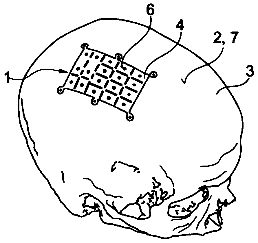
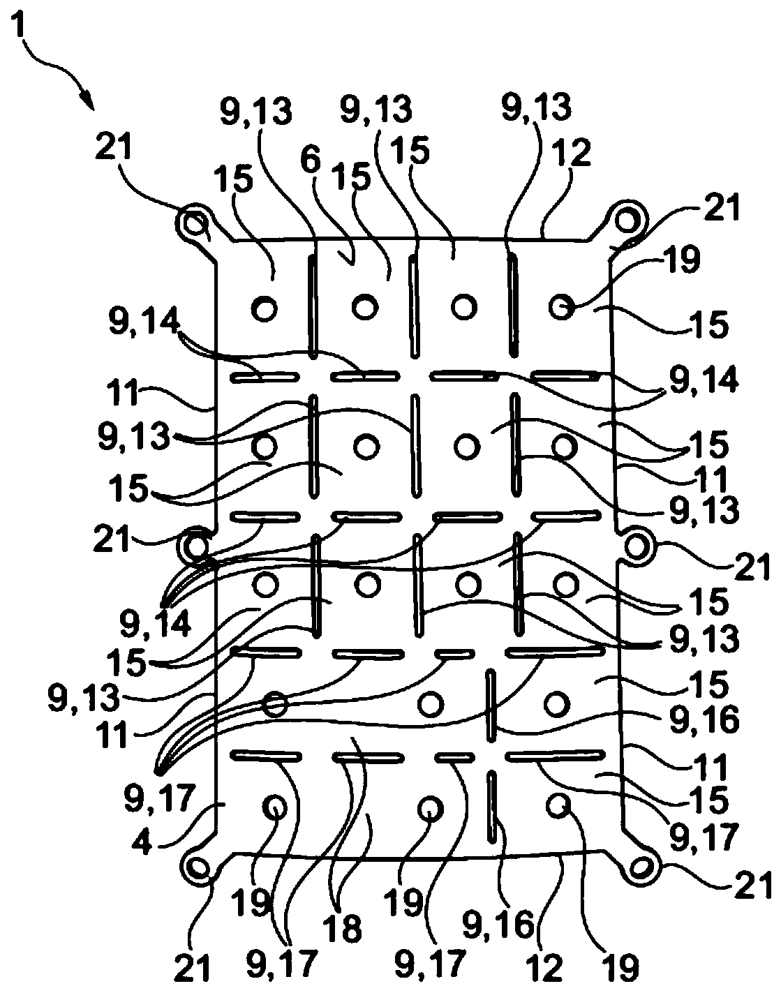
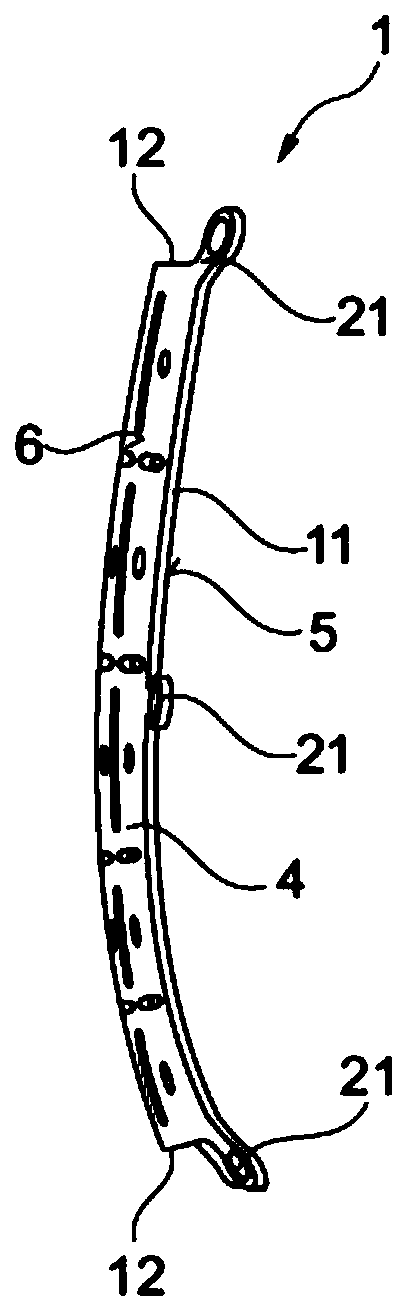
[0039] figure 1 A bone implant 1 according to the invention is shown for attachment at the surface 2 of a human skull 3 . The bone implant 1 has a plate-shaped base body 4 . The underside 5 of the base body 4 is the flat side or surface of the base body 4 which, in the attached state on the skull 3, faces the skull 3 and rests against the skull 3 . on said surface 2 of said skull 3 . The upper side 6 of the basic body 4 is the flat side or surface of the basic body 4 which faces away from the skull 3 in the attached state. The upper side 6 is thus situated opposite the lower side 5 .

[0040] The curvature of the underside 5 corresponds, for example, to the undeformed or defect-free outer contour 7 of the skull 3 . For example, the curvature of the upper side 6 corresponds substantially to the undeformed or defect-free outer contour 7 of the skull 3 . The bone implant 1 thus corresponds to a flat-surfaced bone layer or plate in the skull 3 before bone material is removed ...


PUM


Abstract

The invention relates to a bone implant (1) for attaching to on a surface (2) of a bone (3), including a base body (4) whose lower side (5) and / or upper side (6) correspond(s) substantially to a deformation-free bone outer contour (7), wherein the outer dimensions of the base body (4) are chosen such that the base body (4) covers a specifically introduced deformation region (8) for obtaining autologous bone material completely, wherein in the base body (4) at least one slot (9) is provided which is dimensioned such that it guides a bone marking and / or bone processing tool (10) inserted in theslot (9) in use.

Description

technical field [0001] The present invention relates to a bone implant for repairing or restoring the condition of a bone (osteotomy) and for attachment to a bone, in particular the surface of the skull. Background technique [0002] Bone implants for filling and / or closing defects and / or for repositioning in the skull are known from the prior art. For example, document DE 20 2014 103 858 U1 discloses an implant for reduction and fixation of centrolateral facial fractures (zentrolateralen Mittelgesichtsfraktur), wherein the implant comprises a plurality of preformed segments, preferably three or more pre-shaped segments, wherein the shape of the first segment is designed such that at least its lower side adjacent to the bone is completely or partially complementary to the anatomy of at least a partial region of the outer side of the maxilla wherein the shape of the second segment is such that at least its lower side adjacent to the bone is completely or partially complement...

Claims


Application Information

Patent Timeline
Patent Type & Authority Applications(China)
IPC IPC(8): A61F2/28A61B17/58
CPCA61F2/2875A61B17/58A61F2002/2835A61F2002/30784A61B17/8061A61B2090/3916A61F2310/00011A61B2017/00004A61B17/15A61B17/1739A61B17/1695
Inventor 温格·斯文奈恩阿德姆·阿克苏弗兰克·雷诺尔海纳·怀尔德
Owner KARL LEIBINGER MEDIZINTECHNIK GMBH & CO KG
Why Eureka
Try Eureka