Joining device for friction stirring point, joined article having joined friction stirring point, and shoulder member
A technology of friction stir and shoulder parts, which is applied in the direction of welding/welding/cutting articles, welding equipment, transportation and packaging, etc., can solve the problems of shortening the joining time of the joined objects, and achieve shortening joining time, high joining strength, and increased The effect of joint strength
- Summary
- Abstract
- Description
- Claims
- Application Information
AI Technical Summary
Problems solved by technology
Method used
Image

Examples
Embodiment approach 1
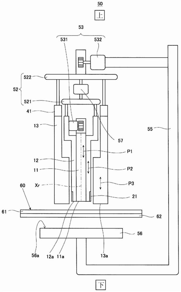
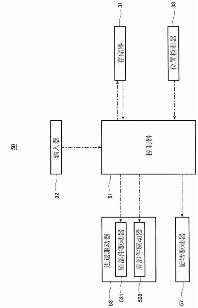
[0058] The friction stir point welding apparatus according to Embodiment 1 includes: a pin member formed in a cylindrical shape; a shoulder member formed in a cylindrical shape through which the pin member is inserted; and a rotary driver that rotates the pin member and the shoulder member. The axis that coincides with the axis of the pin member rotates; and the advance and retreat driver makes the pin member and the shoulder member move forward and backward along the axis respectively, and a slot 1.
[0059] Hereinafter, an example of the friction stir point welding device according to Embodiment 1 will be described in detail with reference to the drawings.
[0060] [Structure of friction stir point joining device]
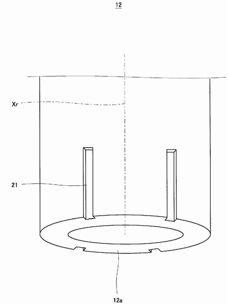
[0061] figure 1 It is a schematic diagram showing the schematic configuration of the friction stir point welding apparatus according to the first embodiment. figure 2 is a schematic representation figure 1 A perspective view of the front end of the shoulder ...
Deformed example 1
[0129] Next, a modified example of the friction stir point welding apparatus according to Embodiment 1 will be described.
[0130] The friction stir spot welding device according to Modification 1 of Embodiment 1 is the friction stir point welding device according to Embodiment 1, in which a second groove is formed on the front end surface of the shoulder member so as to extend in the radial direction.
[0131] Below, refer to Image 6 , the friction stir point welding apparatus according to Modification 1 of Embodiment 1 will be described in detail.
[0132] Image 6 It is a perspective view schematically showing a main part (tip portion of a shoulder member) of a friction stir point welding apparatus according to Modification 1 of Embodiment 1. FIG.
[0133] like Image 6 As shown, the basic structure of the friction stir point welding device according to Modification 1 of Embodiment 1 is the same as that of the friction stir point welding device 50 of Embodiment 1, but i...
Embodiment approach 2
[0137] The friction stir point welding apparatus according to Embodiment 2 includes: a pin member formed in a cylindrical shape; a shoulder member formed in a cylindrical shape through which the pin member is inserted; and a rotary driver that rotates the pin member and the shoulder member. The pin member rotates on the same axis as the axis; and the advance and retreat driver moves the pin member and the shoulder member forward and backward along the axis respectively, and a second groove is formed on the front end surface of the shoulder member to extend radially.
[0138] Below, refer to Figure 7 and Figure 8 , an example of the friction stir point welding device according to Embodiment 2 will be described in detail. In addition, since the operation of the friction stir spot welding device according to Embodiment 2 is basically the same as the operation of the friction stir point welding device according to Embodiment 1, detailed description thereof will be omitted.
[...
PUM
| Property | Measurement | Unit |
|---|---|---|
| size | aaaaa | aaaaa |
| size | aaaaa | aaaaa |
| thickness | aaaaa | aaaaa |
Abstract
Description
Claims
Application Information
 - R&D
- Intellectual Property
- Life Sciences
- Materials
- Tech Scout
- Unparalleled Data Quality
- Higher Quality Content
- 60% Fewer Hallucinations
Browse by: Latest US Patents, China's latest patents, Technical Efficacy Thesaurus, Application Domain, Technology Topic, Popular Technical Reports.
© 2025 PatSnap. All rights reserved.Legal|Privacy policy|Modern Slavery Act Transparency Statement|Sitemap|About US| Contact US: help@patsnap.com