Disposal bag having embossed tie flaps

a tie flap and pouch technology, applied in the field of pouches, can solve the problems of lost or misplaced bags, inconvenient tying of bags, unusable metal wire ties, etc., and achieve the effect of improving the strength of the joined tie flap and the ease of tying

Inactive Publication Date: 2008-11-27
THE GLAD PROD CO
View PDF30 Cites 32 Cited by
  • Summary
  • Abstract
  • Description
  • Claims
  • Application Information

AI Technical Summary

Benefits of technology

The patent text describes a tie bag with improved tie flaps that are easier to handle and stronger than current tie bags. The tie flaps have gripping features that are formed through embossing or other means. The tie bag is made from a flexible plastic material and can be made in a single bag process or a continuous multi-bag process. The tie flaps can be cut and embossed after the bag is formed. The tie bag is designed for tying and has a smooth surface. The technical effects of the patent text include improved ease of bag handling, better tie flap strength, and improved ease of tie flap grasping and tying.

Problems solved by technology

One of the bothersome problems with the use of plain rectangular shaped storage bags is the inconvenience involved in trying to tie the bag closed.
These metal wire ties are unwieldy to use and, as a separate item, are often lost or misplaced from the bags.
It has been determined, however, that the tie flaps of prior art tie bags, are often difficult to grasp and manipulate especially if the tie flaps are contaminated with slippery trash contamination such as oil or grease or moist organic contaminants.

Method used


Image

  • Disposal bag having embossed tie flaps
  • Disposal bag having embossed tie flaps
  • Disposal bag having embossed tie flaps

Examples


Embodiment Construction

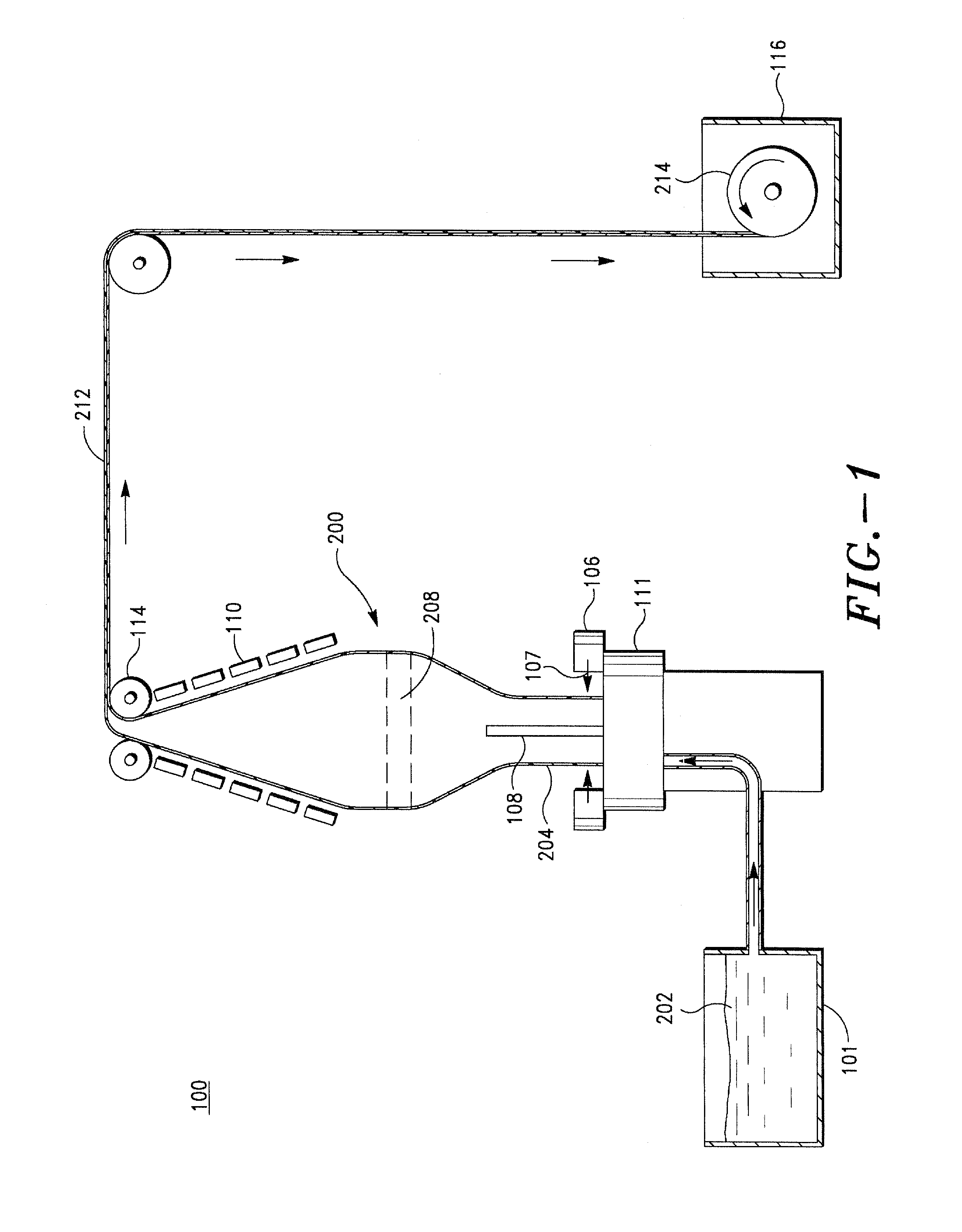
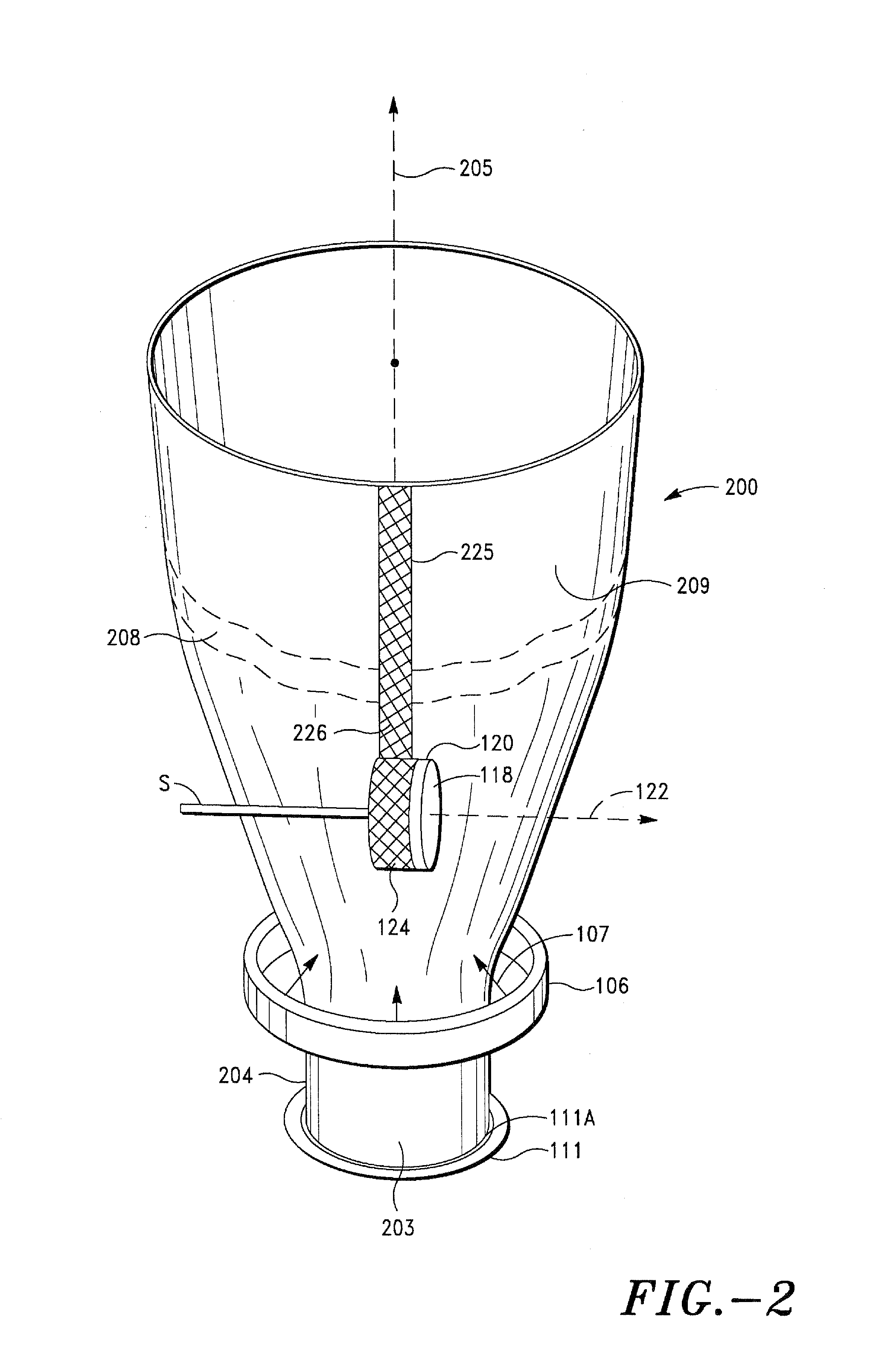
[0025]FIG. 1 shows a schematic sectional, side view of a blow molding extruder 100 used to produce a blow-formed continuous film tube 200 of polyethylene or other thermoplastic material. FIG. 2 shows a perspective view of a portion of the film tube 200 formed in the extruder 100 of FIG. Processes for the manufacture of blown film tubes are generally known. Blown film extrusion processes are described, for example, in U.S. Pat. Nos. 2,409,521, 2,476,140, 2,634,459, 3,750,948, 4,997,616, 5,213,725, and 5,700,489.

[0026]Referring to FIGS. 1 and 2 together, in a blow molding processes, molten plastic melt 202 is first formed in a melt tank 101 of an extruder 100 (FIG. 1). The plastic melt 202 is subsequently compressed in an annular blowing head 111 that has a ring-shaped output gap 111A, usually referred to as a “die”, through which the plastic melt 202 flows.

[0027]In the bag forming process, the plastic melt 202 is extruded from the output gap 111A (FIG. 2) in the blowing head 111 to f...


PUM

PropertyMeasurementUnit
lengthaaaaaaaaaa
lengthaaaaaaaaaa
widthaaaaaaaaaa

Abstract

Provided is a tie bag having at least two tie flaps. The tie bag includes a first sidewall and a second sidewall opposing the first sidewall. The first and second sidewalls are coupled by sealing together three of four corresponding peripheral edges of the sidewalls. The fourth peripheral edge of each of the first and second sidewalls remains unsealed to define an opening in the tie bag. The tie flaps are integral with and extend from the opening of the tie bag and are adapted for tying one to another to close the tie bag and to form a handle for the tie bag. Each of the tie flaps includes gripping features embossed on at least one surface of the tie flaps. The tie bag may be formed from a tube of thermoplastic material.

Description

RELATED APPLICATION[0001]This application claims priority to U.S. Provisional Application No. 60 / 939,136, filed on May 21, 2007, which is hereby incorporated by reference in its entirety.BACKGROUND OF THE INVENTION[0002]1. Field of the Invention[0003]The present invention pertains to bags used most commonly for the storage and disposal of debris and other ubiquitous waste materials and more particularly to disposal tie bags having tie flaps[0004]2. Description of Related Art[0005]The manufacture and use of rectangular shaped thermoplastic storage and disposal bags is well known in the art. One of the bothersome problems with the use of plain rectangular shaped storage bags is the inconvenience involved in trying to tie the bag closed. Several disposal bag brands use twistable metal wire ties, which are packaged separately along with the bags. These metal wire ties are unwieldy to use and, as a separate item, are often lost or misplaced from the bags.[0006]A convenient user feature d...

Claims


Application Information

Patent Timeline
Patent Type & Authority Applications(United States)
IPC IPC(8): B31B49/04B29C47/88B29C47/00B65D33/16B29C49/04B31B70/00B29C48/10B29C48/13B29C48/355
CPCB29C47/0026B29C47/0033B29C47/0038B29C47/0054B29C47/0057B29C47/0059B29C47/0066B29C47/009B29C47/34B29C47/8835B29C2791/007B29C2793/0063B29L2023/001B29L2031/463B29L2031/7128B65D33/1608B29C48/10B29C48/13B29C48/001B29C48/0017B29C48/0018B29C48/0019B29C48/0022B29C48/1472B29C48/355B29C48/913
Inventor SNORECK, CHARLES B.
Owner THE GLAD PROD CO
Why Eureka
Try Eureka