Friction stir spot welding device and method for operating same

A technology of friction stir and operation method, which is applied in the direction of welding equipment, metal processing equipment, manufacturing tools, etc., can solve the problem of shortening the joining time and achieve the effect of shortening the joining time

Pending Publication Date: 2021-12-03
KAWASAKI HEAVY IND LTD
View PDF10 Cites 0 Cited by
  • Summary
  • Abstract
  • Description
  • Claims
  • Application Information

AI Technical Summary

Problems solved by technology

[0005] However, in the method of joining dissimilar metal parts disclosed in the above-mentioned Patent Document 1, there is still room for improvement from the viewpoint of shortening the joining time.

Method used


Image

  • Friction stir spot welding device and method for operating same
  • Friction stir spot welding device and method for operating same
  • Friction stir spot welding device and method for operating same

Examples


Embodiment approach 1

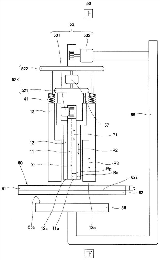
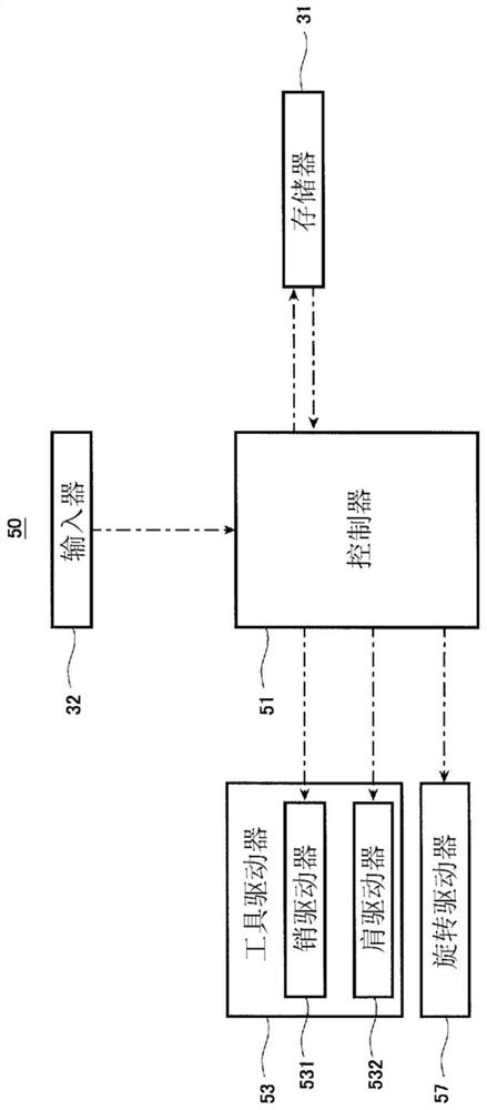
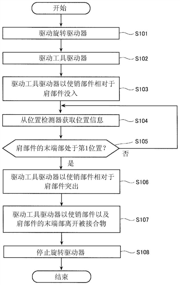
[0030] The friction stir point welding device according to Embodiment 1 is a friction stir point welding device that softens and joins a material to be joined including a first member and a second member by using frictional heat, and the friction stir point welding device includes: a pin member, Formed in a cylindrical shape; a shoulder member, which is formed in a cylindrical shape, and a pin member is inserted inside; a rotary driver, which rotates the pin member and the shoulder member around an axis consistent with the axis of the pin member; an advancing and retreating driver, whose The pin member and the shoulder member are respectively moved forward and backward along the axis; and the controller, the first member is arranged to face the tool and is made of a material with a lower melting point than the second member, and the controller is configured to perform: (A) rotating The driver and the forward and backward driver operate so that the pin member and the shoulder me...


PUM

PropertyMeasurementUnit
Tensile shear strengthaaaaaaaaaa

Abstract

This friction stir pot welding device is provided with: a pin member (11); a shoulder member (12); a rotation driver (57); an advance / retreat driver (53); and a controller (51) that is configured to actuate the advance / retreat driver (53) and the rotation driver (57) so as to cause a tip end of the rotated shoulder member (12) to reach as far as a predetermined first position previously set inside a second member (62) and so that the rotated pin member (11) retreats from a joined section of joined object (60).

Description

technical field [0001] The present invention relates to a friction stir point joining device and its operating method. Background technique [0002] There is known a method of joining dissimilar metal parts by overlapping a first part made of a soft metal and a second part made of a hard metal, and rotating a probe from the side of the first part so that The end thereof is inserted so as to reach directly above the second member, friction stirring is performed, and the first and second members are joined (for example, refer to Patent Document 1). [0003] In the method for joining dissimilar metal parts disclosed in Patent Document 1, a double-action rotary tool is used as a rotary tool in which the probe is independently configured from the shoulder member and can move independently in the axial direction. One component performs friction stir welding of the first and second components. [0004] Patent Document 1: Japanese Patent No. 4937386 [0005] However, in the metho...

Claims


Application Information

Patent Timeline
IPC IPC(8): B23K20/12
CPCB23K20/1245B23K20/123B23K20/125B23K20/1255B23K2103/18
Inventor 大桥良司村松良崇武冈正树三宅将弘
Owner KAWASAKI HEAVY IND LTD
Why Eureka
Try Eureka