
Workpiece Image Defogging Method and Device Applied to Ion Beam Precise Coating

An image and image input technology, applied in the field of image processing, can solve the problems of poor image accuracy and poor generality of the blind dehazing model.

Active Publication Date: 2020-07-31
BEIJING UNIV OF POSTS & TELECOMM
View PDF10 Cites 0 Cited by
  • Summary
  • Abstract
  • Description
  • Claims
  • Application Information

AI Technical Summary

Problems solved by technology

[0004] However, when using the existing technology to defog the image, since most of the priors of the blur kernels are statistically obtained, this will lead to poor versatility of the blind defog model, making the image defog is also less accurate

Method used


Image

  • Workpiece Image Defogging Method and Device Applied to Ion Beam Precise Coating
  • Workpiece Image Defogging Method and Device Applied to Ion Beam Precise Coating
  • Workpiece Image Defogging Method and Device Applied to Ion Beam Precise Coating

Examples


Embodiment Construction

[0079] The following will clearly and completely describe the technical solutions in the embodiments of the present invention with reference to the accompanying drawings in the embodiments of the present invention. Obviously, the described embodiments are only some, not all, embodiments of the present invention. Based on the embodiments of the present invention, all other embodiments obtained by persons of ordinary skill in the art without making creative efforts belong to the protection scope of the present invention.

[0080] In order to improve the versatility of the blind dehazing model, thereby improving the accuracy of dehazing images, embodiments of the present invention provide an image dehazing method, device, and electronic equipment.

[0081] The image defogging method provided by the embodiment of the present invention is firstly introduced below.

[0082] It should be noted that the image defogging method provided by the embodiment of the present invention can be ...


PUM


Abstract

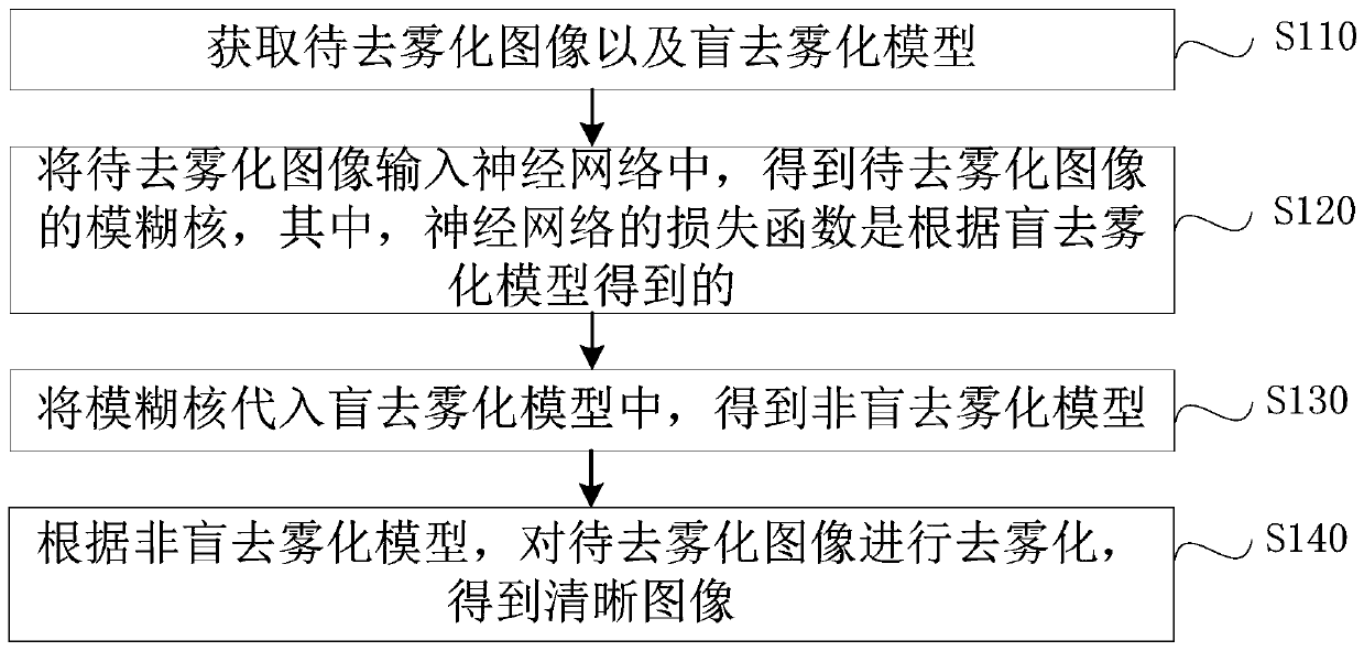
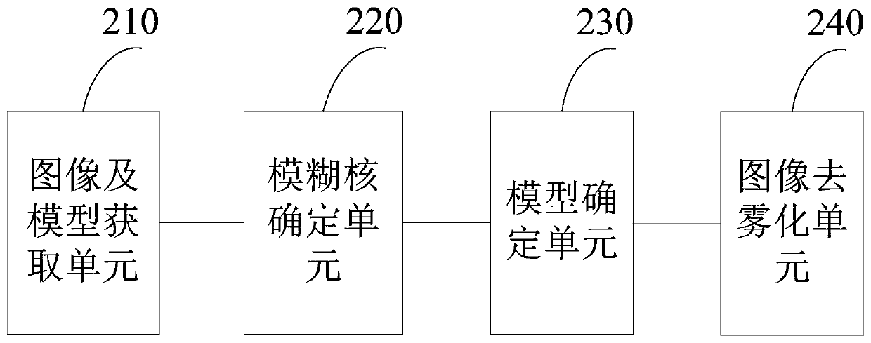
Embodiments of the present invention provide an image defogging method, device, and electronic equipment, wherein the method includes: acquiring an image to be defogged and a blind defogging model; inputting the image to be defogged into a neural network, The blur kernel of the image to be defogged is obtained, wherein the loss function of the neural network is obtained according to the blind defogged model, and the blind defogged model includes: a dark channel prior; Substituting the fuzzy kernel into the blind defogging model to obtain a non-blind defogging model; according to the non-blind defogging model, defogging is performed on the image to be defogged to obtain a clear image. Adopting the technical solutions provided by the embodiments of the present invention can improve the versatility of the blind defogging model when defogging images, thereby improving the accuracy of defogging images.

Description

technical field [0001] The present invention relates to the technical field of image processing, in particular to an image defogging method, device and electronic equipment. Background technique [0002] During the image capturing process, due to the light problem of the shooting environment or the problem of the object to be shot, it is easy to make the captured image blurred. In many cases, when the captured image is blurred, it is necessary to perform defog processing on the captured image to obtain a clear image. For example, in the process of ion beam sputtering coating, it is necessary to take images of workpieces to be processed, and position the workpieces to be processed according to the captured images, so as to adjust the positions between the ion source, the workpieces to be processed and the target platform, so that the sputtering The ions can be aimed at the workpiece to be processed, but because the light in the operating room of the ion beam sputtering coati...

Claims


Application Information

Patent Timeline
Patent Type & Authority Patents(China)
IPC IPC(8): G06T5/00G06N3/04G06N3/08
CPCG06T5/003G06T5/002G06N3/084G06T2207/20084G06T2207/20081G06N3/045
Inventor 景晓军黄海杨威刁克明张芳沛王雪姝
Owner BEIJING UNIV OF POSTS & TELECOMM
Learn More