Cooler with variable cooling efficiency

A technology of cooling efficiency and coolers, applied in the direction of machines/engines, exhaust gas recirculation, mechanical equipment, etc., can solve the problems of increasing production costs and waste of coolers, and achieve the effect of reducing waste, reducing waste, and convenient replacement of parts

Pending Publication Date: 2020-03-06
WUXI LONGSHENG TECH
View PDF0 Cites 0 Cited by
  • Summary
  • Abstract
  • Description
  • Claims
  • Application Information

AI Technical Summary

Problems solved by technology

[0005] The technical problem to be solved by the present invention is to provide a cooler with variable cooling efficiency, so as to solve the problem that the existing cooler cannot adjust the cooling efficiency, which causes the waste of the cooler and increases the production cost. The purpose of adjusting the cooling efficiency of the cooler is to ensure that the required cooling efficiency is different without replacing the entire cooler, reducing the waste of the cooler, reducing the waste of cooler production molds, and reducing production costs

Method used


Image

  • Cooler with variable cooling efficiency
  • Cooler with variable cooling efficiency
  • Cooler with variable cooling efficiency

Examples


Embodiment Construction

[0023] The present invention will be further described in detail below in combination with specific embodiments.

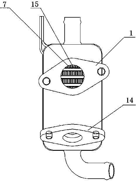
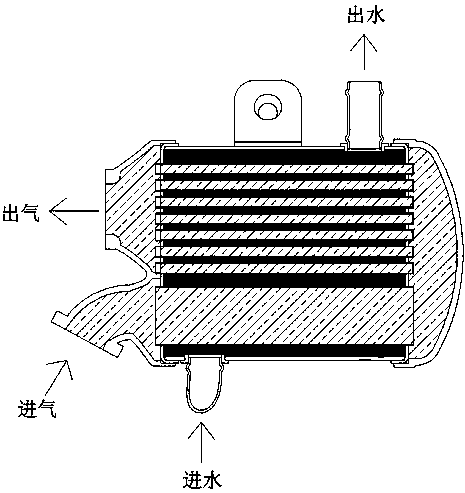
[0024] A variable cooling efficiency cooler that combines Figure 1 to Figure 5 As shown, it includes a housing 9, a flange-shaped cover plate 6, an air inlet pipe 12, an air outlet pipe 13, a fixed plate 2, a water inlet pipe 11, an outlet pipe 4, a preliminary cooling structure and a secondary cooling structure.

[0025] A flange-shaped cover plate 6 is provided on the right end of the housing 9 .

[0026] The inlet pipe 12 and the outlet pipe 13 are arranged at the left end of the housing 9 and are not connected to each other. The inlet pipe 12 is used to pass through the exhaust gas to be cooled, and the outlet pipe 13 is used to output the cooled exhaust gas. The air inlet pipe 12 and the air outlet pipe 13 provided can ensure the circulation of exhaust gas.

[0027] An air inlet flange 14 is arranged at the end of the air inlet pipe 12 , and an air outlet ...


PUM


Abstract

The invention discloses a cooler with variable cooling efficiency. The cooler comprises a shell, a flange-shaped cover plate is arranged at the right end of the shell in a covering manner, and an airinlet pipe and an air outlet pipe are arranged at the left end of the shell. Two fixed plates are vertically arranged on the inner wall of the shell at an interval. A waste gas temporary storage cavity is formed between the fixed plate on the right side and the flange-shaped cover plate. A cooling water cavity is defined among the two fixed plates and the inner wall of the shell. A water outlet pipe and a water inlet pipe are arranged at the upper end and the lower end of the shell correspondingly. A primary cooling structure and a secondary cooling structure are sequentially and detachably connected between the two fixed plates. The left end of the primary cooling structure communicates with the air inlet pipe, and the left end of the primary cooling structure communicates with the air outlet pipe. The right end of the primary cooling structure and the right end of the secondary cooling structure communicate with the waste gas temporary storage cavity. According to the cooler, the cooling efficiency can be adjusted by replacing an inner pipe, a fin and a ventilating straight pipe without changing cooler producing mold.

Description

technical field [0001] The invention relates to the technical field of engine exhaust emission recirculation system. Background technique [0002] The EGR valve in the engine exhaust gas recirculation system (EGR system) is mainly used to adjust and control the flow of recirculated exhaust gas. The electric EGR valve controls the opening of the intake port through the internal DC motor, thereby indirectly controlling the opening of the EGR. To adjust the exhaust gas flow, so that the exhaust gas and fresh air are mixed in a certain proportion and then returned to the cylinder for recirculation, so as to reduce the combustion temperature and combustion speed in the cylinder, and further reduce NO X emissions. The EGR cooler is used to reduce the engine intake temperature, thereby reducing the combustion temperature and further reducing NO X At the same time, it can reduce the temperature entering the EGR valve to meet the temperature resistance level of the EGR valve itself...

Claims


Application Information

Patent Timeline
Patent Type & Authority Applications(China)
IPC IPC(8): F02M26/28F02M26/32F02M26/33F01N3/02
CPCF01N3/0205F02M26/28F02M26/32F02M26/33
Inventor 施爱峰
Owner WUXI LONGSHENG TECH
Why Eureka
Try Eureka