Anaerobic fermentation system based on synergistic gas spray pipe

An anaerobic fermentation tank and gas technology, which is applied in the field of solid waste disposal and resource utilization in environmental engineering, can solve problems such as unfavorable stable operation and commissioning and start-up, reduce the effective volume of the tank, prolong the maintenance time of tank cleaning, etc., and achieve easy automation The effect of control, high energy utilization rate, and less labor requirements

Pending Publication Date: 2020-03-06
RES CENT FOR ECO ENVIRONMENTAL SCI THE CHINESE ACAD OF SCI
View PDF0 Cites 0 Cited by
  • Summary
  • Abstract
  • Description
  • Claims
  • Application Information

AI Technical Summary

Problems solved by technology

However, the structural design of the current biogas mixing system is still insufficient. The outlet nozzle of the biogas delivery pipe is designed to penetrate deep into the anaerobic tank and protrude from the bottom surface of the tank for a certain distance, so that the materials around the protruding pipeline cannot be blown up by the pressurized gas well, resulting in The material is easy to accumulate in this area, and the effective volume of the tank will be reduced after long-term operation; for the cleaning and maintenance of the accumulated material, mechanical vehicles cannot be used due to the densely covered pointed nozzles protruding from the surface of the tank, and the tank needs to be cleaned manually, which greatly Prolonged tank cleaning maintenance time, resulting in long shutdown of the project, which is not conducive to stable operation and commissioning start

Method used


Image

  • Anaerobic fermentation system based on synergistic gas spray pipe
  • Anaerobic fermentation system based on synergistic gas spray pipe
  • Anaerobic fermentation system based on synergistic gas spray pipe

Examples


Embodiment 1

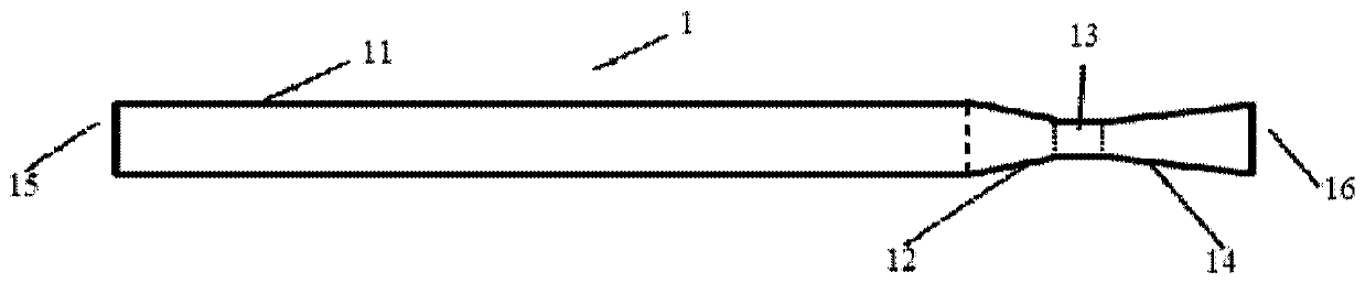
[0035] In a first exemplary embodiment of the present invention there is provided a booster gas nozzle such as figure 1 As shown, the synergistic gas nozzle 1 includes a main pipe section 11, a diameter reducing section 12, a throat section 13 and an expanding section 14 connected in sequence, wherein,

[0036] The main pipe section 11, the free end of the main pipe section 11 is set as an air inlet 15;

[0037] Reduced diameter section 12, the two ends of the reduced diameter section 12 are respectively connected with the main pipe section 11 and the throat section 13, the inner diameter of the reduced diameter section 12 gradually decreases from the main pipe section 11 to the throat section 13, and is used to accelerate the transported gas ;

[0038] A throat section 13, the two ends of the throat section 13 are respectively connected to the diameter-reducing section 12 and the expanding section 14;

[0039] An expansion section 14, the free end of the expansion section 1...

Embodiment 2

[0052] In the second exemplary embodiment of the present invention, as an aspect of the present invention, an anaerobic fermentation tank is also provided, and the anaerobic fermentation tank includes:

[0053] tank;

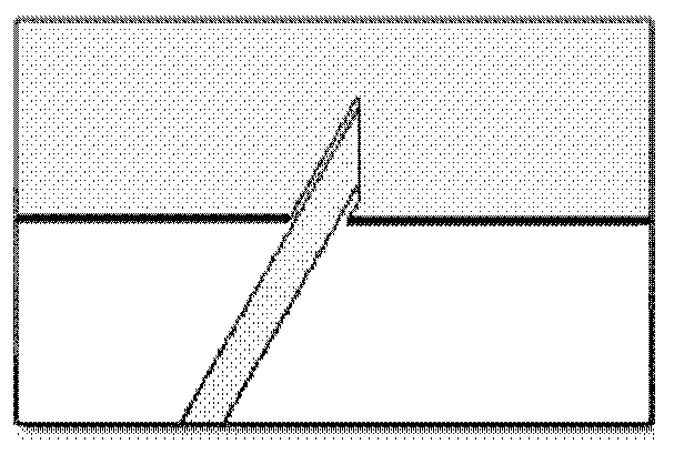
[0054] Like the synergistic gas nozzle 1 mentioned above, the end of the gas outlet 16 of the synergistic gas nozzle 1 is flush with the bottom of the tank; and the synergistic gas nozzle 1 is arranged at an angle with the horizontal plane.

[0055] More specifically, in order to make the efficient implementation of the gas stirring of the present invention, as Figure 3D As shown, the synergistic gas nozzle 1 needs to be assembled with the anaerobic fermentation tank, the synergistic gas nozzle 1 is connected to the bottom of the anaerobic fermentation tank, the upper part of the synergistic gas nozzle 1 is embedded in the bottom of the fermenter, and the synergistic gas nozzle The air outlet 16 of 1 is flush with the inner surface of the bottom of the anaerob...

Embodiment 3

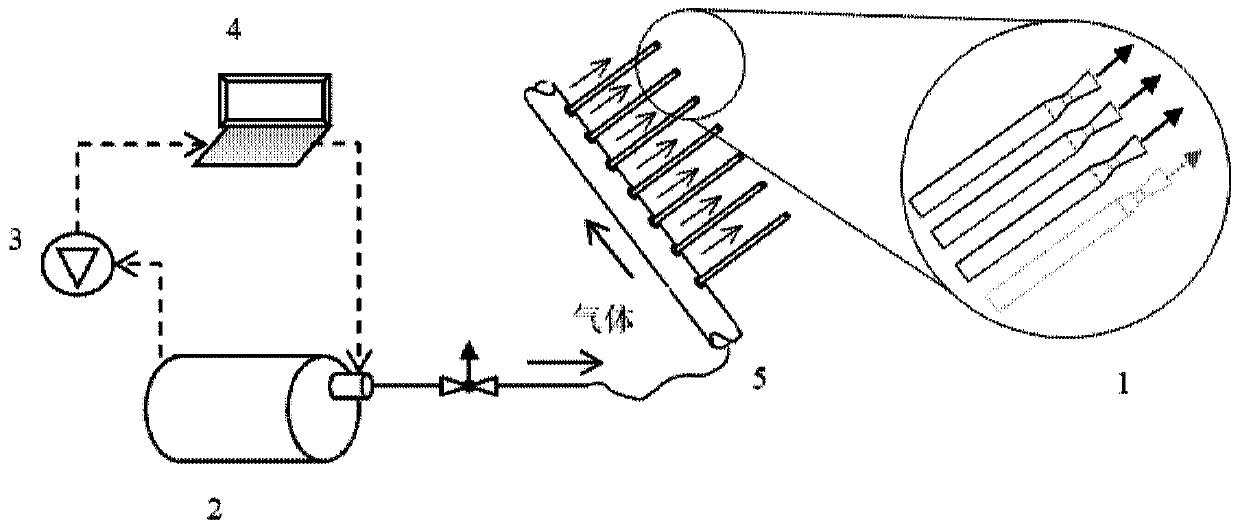
[0071] In a third exemplary embodiment of the present invention, an anaerobic fermentation system is also provided, such as figure 2 shown, including

[0072] As above-mentioned anaerobic fermenter, be used for carrying out anaerobic fermentation;

[0073] The pressure storage unit is used to store the pressure of the gas volume, store energy for the gas injection, and deliver the accelerated gas to the tank through the synergistic gas nozzle 1, so as to realize the material stirring in the tank;

[0074] The monitoring unit is used to measure the pressure value of the pressure reserve unit in real time;

[0075] The control unit is used for obtaining and analyzing the pressure value measured by the monitoring unit, and controlling the operation of the pressure reserve unit.

[0076] In an embodiment of the present invention, the pressure reserve unit includes:

[0077] Gas pressure storage tank 2, used to store compressed gas;

[0078] Large-resistance gas distribution p...


PUM


Abstract

The invention discloses an anaerobic fermentation system based on a synergistic gas spray pipe. The synergistic gas spray pipe comprises a main pipe section, a reducing section, a throat pipe sectionand an expansion section which are connected in sequence. According to the synergistic gas spray pipe disclosed by the invention, a higher gas flow rate can be obtained after gas at the inlet passes through the synergistic gas spray pipe, so that the stirring and mixing capacity of materials in an anaerobic fermentation tank can be effectively improved, and the energy consumption is reduced. Through reasonable assembly of the synergistic gas spray pipe and the anaerobic fermentation tank, the operation and maintenance interval time of the high-solid-content / dry-type anaerobic engineering is prolonged, and the tank cleaning time during maintenance can also be shortened. The efficient gas stirring device disclosed by the invention can be used for a material stirring process of high-solid-content and dry-type anaerobic fermentation tanks in an operation process, promotes the mixing homogenization and the hard layering of high-concentration materials in the anaerobic fermentation tank, andis convenient for restarting the anaerobic fermentation tank which are shut down. Compared with mechanical stirring devices and previous gas stirring devices, the device has the characteristics of economy, high efficiency and high applicability.

Description

technical field [0001] The invention relates to the technical field of environmental engineering solid waste disposal and recycling, in particular to an anaerobic fermentation system based on a synergistic gas nozzle. Background technique [0002] Compared with the wet anaerobic digestion process, the high solids / dry anaerobic fermentation has a stronger processing load, a higher volumetric gas production rate, water saving, less biogas slurry production or no discharge of biogas slurry, simple post-treatment and operating costs Low-level advantages, it is increasingly used in the treatment of organic solid waste such as livestock and poultry waste and kitchen waste in Europe and other foreign economically developed markets. In recent years, dry anaerobic fermentation technology has also been used more in China. To alleviate the contradiction between the demand for recycling policies and the gap in the processing capacity of organic solid waste such as domestic waste. [00...

Claims


Application Information

Patent Timeline
Patent Type & Authority Applications(China)
IPC IPC(8): C12M1/04C12M1/02C12M1/107
CPCC12M21/04C12M27/02C12M29/06
Inventor 魏源送郑嘉熹柳蒙蒙刘吉宝陈梅雪王亚炜郁达伟
Owner RES CENT FOR ECO ENVIRONMENTAL SCI THE CHINESE ACAD OF SCI
Why Eureka
Try Eureka