Tempered glass partition mounting structure and method

A technology of tempered glass and installation structure, which is applied in the direction of building components, building structures, walls, etc. It can solve the problems that the base structure is not strong enough, the base layer requirements are not high, and affect the construction efficiency, so as to shorten the construction period, improve the lighting, The effect of eliminating potential safety hazards

Pending Publication Date: 2020-02-28
GOLD MANTIS FINE DECORATION TECH SUZHOU CO LTD
View PDF0 Cites 0 Cited by
  • Summary
  • Abstract
  • Description
  • Claims
  • Application Information

AI Technical Summary

Problems solved by technology

[0002] At present, in the field of decorative partitions for indoor corridors, light steel keel partition walls are usually used as partitions. Such partitions do not have high requirements for the base layer. Generally, light steel keels are sufficient, but ultra-white tempered glass with a large self-weight is used as indoor corridors. The decorative partition of the channel has much higher requirements on the base layer. If the general bottom base layer is used, the base structure may not be firm enough and a large area may be inclined, causing irreparable losses.
[0003] After the current ultra-clear tempered glass partition is installed, the distance between the two pieces of glass cannot be fine-tuned. Due to the error in the processing of the ground and base-level profiles, there will be an error of a few millimeters in the installation thickness. In some precision requirements In the high installation area, these errors must be adjusted, which will lead to the need to remove the partition and reprocess the profile to overcome the error. The adjustment is very troublesome and affects the overall construction efficiency

Method used


Image

  • Tempered glass partition mounting structure and method

Examples


Embodiment 1

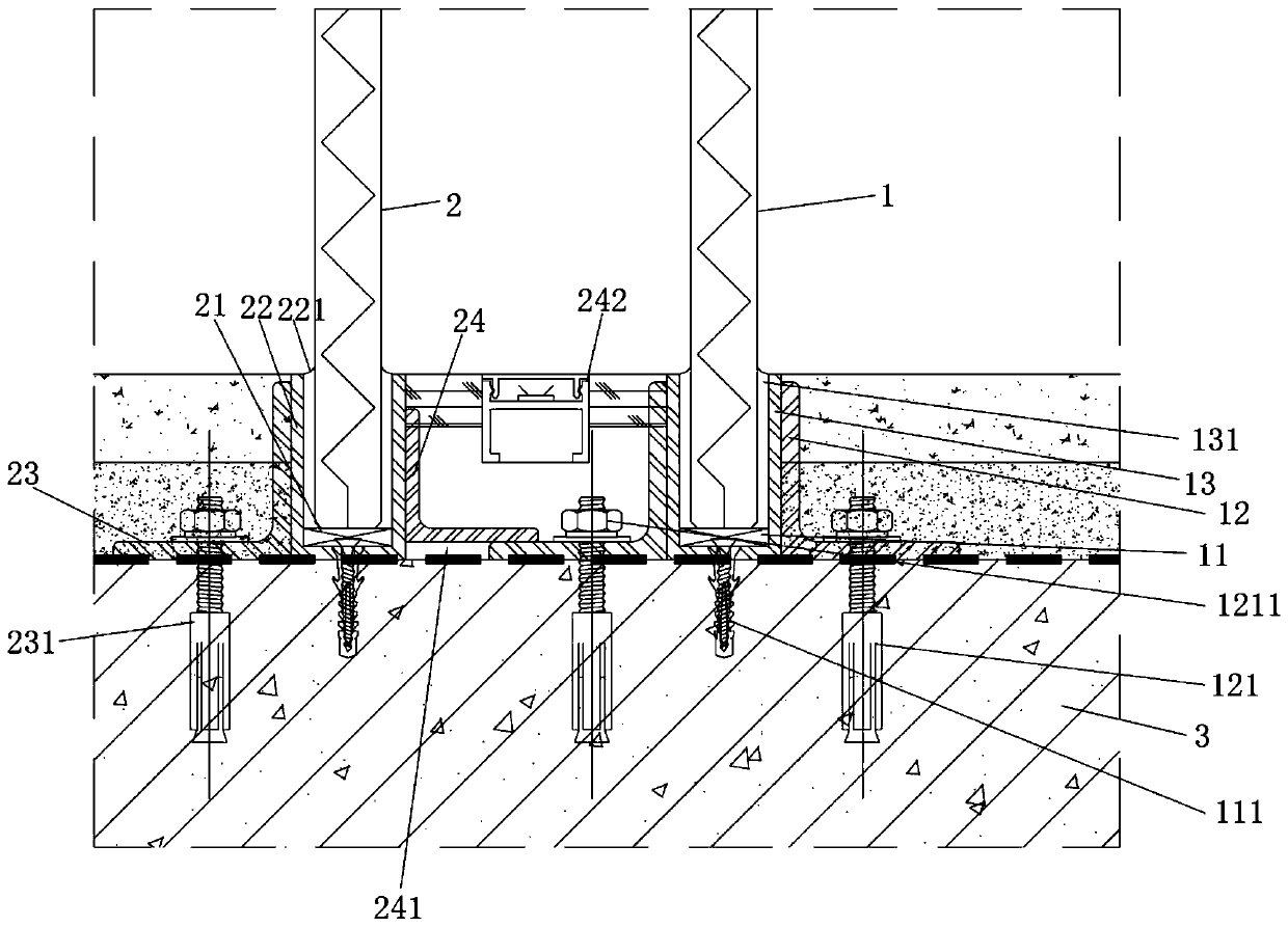
[0029] see figure 1 , the figure shows a tempered glass partition installation structure provided by Embodiment 1 of the present invention, which includes a first tempered glass 1 and a second tempered glass 2, the bottom of the first tempered glass 1 is fitted with a glass clamp 11 (specifically The cross-section is a U-shaped strip), the bottom of the glass clamp 11 is fixedly connected to the building ground 3, and the outer and inner sides of the first tempered glass 1 are respectively provided with two first steel plates 12, and the first steel plates 12 are fixedly connected to the building. On the ground 3, the bottom of the first tempered glass 1 is sandwiched between two first steel plates 12, a cavity 4 is left between the second tempered glass 2 and the first tempered glass 1, and the inner side of the first tempered glass 1 faces the void. Cavity 4, the bottom of the second tempered glass 2 is fitted with an elastic glass clip 21 (specifically a U-shaped strip in c...

Embodiment 2

[0042] see figure 1 , the figure shows a tempered glass partition installation structure provided by Embodiment 2 of the present invention. On the basis of the above-mentioned embodiments, this embodiment further makes the following technical solutions as improvements: the third steel plate 24 is The cross-section is an L-shaped angle steel, and the cross-sectional area of ​​the third steel plate 24 is smaller than that of the second steel plate 23 . Through the setting of the above structure, under the condition of ensuring the inner strength of the second tempered glass, the weight burden on the inner side of the second tempered glass can be reduced, thereby facilitating the fine adjustment of the distance between the second tempered glass and the first tempered glass.

Embodiment 3

[0044] see figure 1 , the figure shows a tempered glass partition installation structure provided by Embodiment 3 of the present invention. On the basis of the above-mentioned embodiments, this embodiment further makes the following technical solutions as improvements: the third steel plate 24 The bottom rests on the bottom of the first steel plate 12, and a space is formed between the bottom surface of the third steel plate 24 and the building ground 3, and an elastic rubber block 241 is arranged in the space. Through the setting of the above structure, the elastic rubber block can form a limit function for fine-tuning the distance between the second tempered glass and the first tempered glass, so as to ensure that the firmness of the second tempered glass base layer will not be affected by excessive adjustment.


PUM


Abstract

The invention provides a tempered glass partition mounting structure. The tempered glass partition mounting structure comprises first tempered glass and second tempered glass; two first steel plates are arranged on the outer side and the inner side of the first tempered glass respectively and are fixedly connected to the building ground; the bottom of the second tempered glass is sleeved with an elastic glass clamp and a first elastic packaging sleeve; a second steel plate and a third steel plate are arranged on the inner side and the outer side of the first elastic packaging sleeve respectively; the second steel plate is fixedly connected to the building ground; the third steel plate is located in a cavity; and the side surface of the third steel plate is fixedly connected to the inner side surface of the first elastic packaging sleeve. The invention further provides a mounting method. Compared with the prior art, the method has the advantages that mounting of vitrified bricks for slope modeling can be completed quickly, and slope adjustment is quicker and more accurate. According to the tempered glass partition mounting structure, efficient fine adjustment of the glass partitionmounting thickness can be realized, a partition is not required to be dismounted, profiles are not required to be machined again, and the construction efficiency of the partition can be improved.

Description

technical field [0001] The invention relates to a tempered glass partition installation structure, in particular to a tempered glass partition installation structure and method, wherein the tempered glass specifically refers to ultra-clear tempered glass. Background technique [0002] At present, in the field of decorative partitions for indoor corridors, light steel keel partition walls are usually used as partitions. Such partitions do not have high requirements for the base layer. Generally, light steel keels are sufficient, but ultra-white tempered glass with a large self-weight is used as indoor corridors. The decorative partition of the channel has much higher requirements on the base layer. If a general bottom base layer is used, the base structure may not be firm enough and a large area may be inclined, causing irreparable losses. [0003] After the current ultra-clear tempered glass partition is installed, the distance between the two pieces of glass cannot be fine-...

Claims


Application Information

Patent Timeline
IPC IPC(8): E04B2/74E04B2/82
CPCE04B2/7455E04B2/82
Inventor 车涛涛王世鑫杨甜甜袁学勇张冬奇吴海燕赵士勇吕晓麟张学应张羽史佳兴吴艳阳贾傲
Owner GOLD MANTIS FINE DECORATION TECH SUZHOU CO LTD
Why Eureka
Try Eureka