Dustproof drying device for textile processing

A drying device and dust-proof technology, applied in the field of textile processing, can solve the problems of dust, detachment, and harm to the working environment, etc., and achieve the effects of improving drying rate, improving dust-absorbing ability, and preventing clogging.

Inactive Publication Date: 2020-02-21
天门友承服饰有限公司
View PDF1 Cites 1 Cited by
  • Summary
  • Abstract
  • Description
  • Claims
  • Application Information

AI Technical Summary

Problems solved by technology

[0002] With the rapid development of the market economy, automation equipment is becoming more and more popular, and people are becoming more and more automated when processing textiles. Existing textiles need to be rinsed and then dried during the processing process. During drying, the dust attached to the textiles and The textile itself may be detached, after drying, open the drying box, a large amount of dust may affect the health of the staff
[0003] After retrieval, the Chinese patent application number is CN201721732746.7, which discloses a high-efficiency textile processing and production drying device, including a device body. The interior of the device body is separated by a partition for a textile processing area, and the textile processing area The lower end is provided with a textile drying area, the upper end of the textile processing area is provided with a textile feeding port, the left end of the heating wire placement platform is provided with a pipe support device, the outer ring of the pipe is fixed with a blower, and the textile drying area There is an air outlet on the right side of the textile processing area, and a driving device is installed on the left end of the textile processing area. In this high-efficiency textile processing and production drying device, the textile body is arranged on the outer ring of the roller shaft, which is conducive to orderly entering the textile body into the textile. The interior of the drying area avoids the entanglement of the textile body. Install a slideway inside the textile drying area to facilitate entry into the textile drying area. Your internal textile body slides down smoothly through the slideway, which is conducive to increasing the drying of the textile body. Although the above-mentioned patents have enhanced the drying rate of textiles, they cannot solve the large amount of dust generated during the drying process of textiles, which endangers the working environment.

Method used


Image

  • Dustproof drying device for textile processing
  • Dustproof drying device for textile processing
  • Dustproof drying device for textile processing

Examples


Embodiment 1

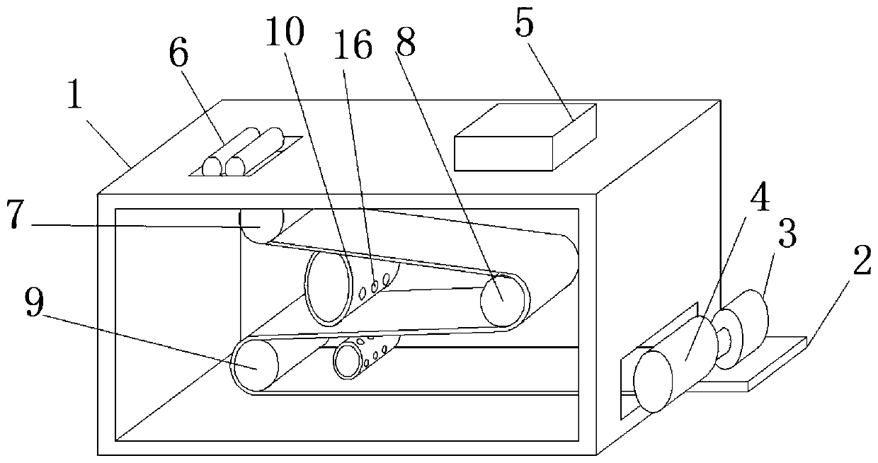
[0027] refer to Figure 1-2 , a dust-proof drying device for textile processing, comprising a box body 1, two circular through holes are opened on one side of the inner wall of the box body 1, and a dust collection box 11 is welded at the circular through holes of the box body 1 One end of the dust collection box 11 is welded with the external negative pressure fan system, the two sides of the top of the dust collection box 11 are welded with support rods 14, one end of the dust collection box 11 is welded with a dust collection cylinder 10 outside, and the dust collection box 11 is welded to the outside. The outside of the dust cylinder 10 is provided with several suction holes 16, the top of the pole 14 is provided with a drum 12, and the bottom of the drum 12 is provided with a sliding groove, and the drum 12 and the pole 14 are slidably connected at the sliding groove , the exterior of the drum 12 is provided with several through holes, the exterior of the drum 12 is welde...

Embodiment 2

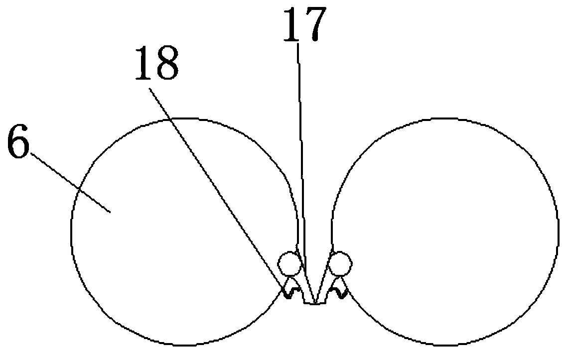
[0032] refer to image 3 , a dust-proof drying device for textile processing. Compared with Embodiment 1, this embodiment is in order to prevent the textile from being damaged due to the influence of friction between the extrusion rod and the extrusion rod when it is squeezed. 6 is welded with an arc-shaped scraper 17, and one side of the arc-shaped scraper 17 is rotationally connected with the extruding rod 6. A spring 18 is welded between the arc-shaped scraper 17 and the extruding rod 6. When the textile is extruded When working, the contact area between the two scrapers 17 and the textiles becomes smaller, which increases the pressure received by the textiles and makes it easier for the water to be squeezed out. In addition, the elastic limit of the spring 18 prevents the textiles from contacting the extrusion rod The friction between 6 is too large, which may lead to the occurrence of textile damage.

[0033]Working principle: Turn on the DMJ-30 type hot air blower 5 to ...


PUM


Abstract

The invention discloses a dustproof drying device for textile processing. The box comprises a box body, wherein two circular through holes are formed in one side of the inner wall of the box body; thebox body is fixedly connected with a dust collection box at the circular through holes, and one end of the dust collection box is fixedly connected with an external negative pressure fan system; supporting rods are fixedly connected to two sides of the top end of the dust collection box, and a dust collection cylinder is fixedly connected to the outside of one end of the dust collection box; a plurality of dust collection holes are formed in the outside of the dust collection cylinder, and a rotary drum is arranged at the top end of each supporting rod; the bottom end of each rotary drum is provided with a sliding groove, and each rotary drum is in sliding connection with the corresponding supporting rod at the corresponding sliding groove; the outer part of each rotary drum is provided with a plurality of through holes, and the outer part of each rotary drum is fixedly connected with a hard bristle brush ring at one sides of the dust collection holes. Compared with an existing device, the dustproof drying device for textile processing has the advantages that by arrangement of the dust collection box, air flow inside the box body is driven to move by starting an air heater and thenegative pressure fan, fan blades are driven to rotate, the fan blades drive the rotary drums to clean the dust collection holes of the dust collection cylinder, and the dust collection capacity of the device is improved.

Description

technical field [0001] The invention relates to the technical field of textile processing, in particular to a dust-proof drying device for textile processing. Background technique [0002] With the rapid development of the market economy, automation equipment is becoming more and more popular, and people are becoming more and more automated when processing textiles. Existing textiles need to be rinsed and then dried during the processing process. During drying, the dust attached to the textiles and The textile itself may be detached, and after drying, the drying oven is opened, and a large amount of dust may affect the health of the staff. [0003] After retrieval, the Chinese patent application number is CN201721732746.7, which discloses a high-efficiency textile processing and production drying device, including a device body. The interior of the device body is separated by a partition for a textile processing area, and the textile processing area The lower end is provide...

Claims


Application Information

Patent Timeline
Patent Type & Authority Applications(China)
IPC IPC(8): D06B15/02D06B15/08D06B15/09D06B23/20D06B23/30
CPCD06B15/02D06B15/085D06B15/09D06B23/20D06B23/30
Inventor 余本艳
Owner 天门友承服饰有限公司
Why Eureka
Try Eureka